|
#31
 17-07-12, 14:38
|
||||
|
||||
|
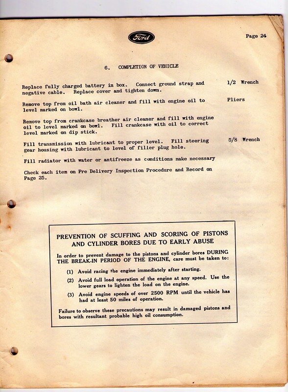
Don't forget the oil! And don't wreck the nice new motor either...
__________________
Film maker 42 FGT No8 (Aust) remains 42 FGT No9 (Aust) 42 F15 Keith Webb Macleod, Victoria Australia Also Canadian Military Pattern Vehicles group on Facebook https://www.facebook.com/groups/canadianmilitarypattern 
|
|
#32
17-07-12, 14:39
|
||||
|
||||
|
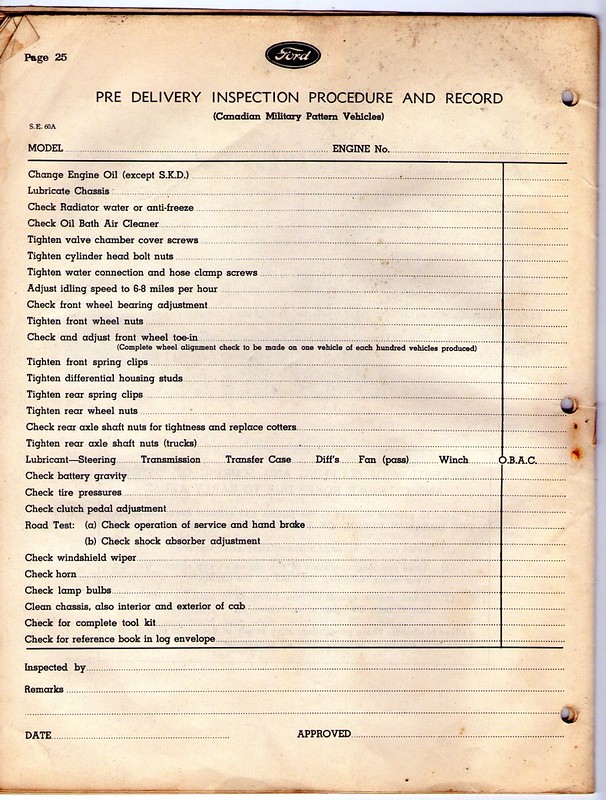
Checklist...
__________________
Film maker 42 FGT No8 (Aust) remains 42 FGT No9 (Aust) 42 F15 Keith Webb Macleod, Victoria Australia Also Canadian Military Pattern Vehicles group on Facebook https://www.facebook.com/groups/canadianmilitarypattern
|
|
#33
17-07-12, 14:40
|
||||
|
||||
|
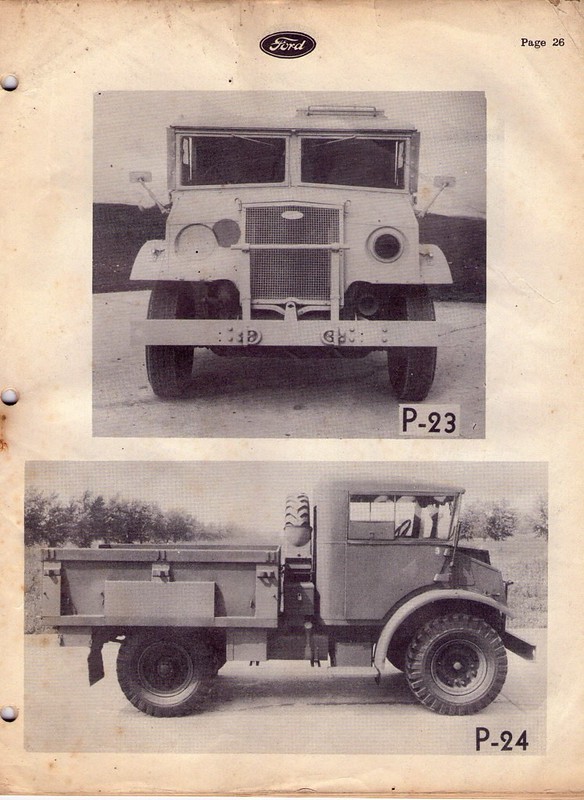
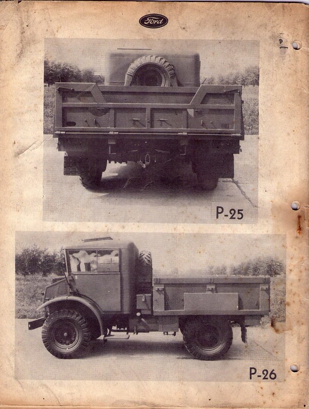
Your nice new F15!
__________________
Film maker 42 FGT No8 (Aust) remains 42 FGT No9 (Aust) 42 F15 Keith Webb Macleod, Victoria Australia Also Canadian Military Pattern Vehicles group on Facebook https://www.facebook.com/groups/canadianmilitarypattern
|
|
#34
17-07-12, 14:42
|
||||
|
||||
|
Here endeth the lesson... hope you enjoyed it, and thanks again to Diego for sharing this with us. We hope to see you here soon on MLU!
__________________
Film maker 42 FGT No8 (Aust) remains 42 FGT No9 (Aust) 42 F15 Keith Webb Macleod, Victoria Australia Also Canadian Military Pattern Vehicles group on Facebook https://www.facebook.com/groups/canadianmilitarypattern
|
|
#35
17-07-12, 14:58
|
||||
|
||||
|
That really is the find of all finds....
What I love most about it is I will very soon be reassembling that very same type of truck. Dont have to worry about where Ive put the bits - I'll just follow the instructions Excellent work Diego and Keefy
__________________
Pax Vobiscum.......may you eat three meals a day & have regular bowel movements.
|
|
#36
03-03-14, 02:47
|
||||
|
||||
|
Excellent reference. Thank-you.
|
|
#37
10-03-14, 03:58
|
||||
|
||||
|
Gents,
I know it is an old tread but wow , fantastic ! Incredible ,i own this exact same truck model. The contemporary details i had never seen before. This will help me with some finishing details i was missing. Thanks for posting ! Your friend from Canada , were they all came from in the first place . 
__________________
44 GPW / 44 C-15-A Cab 13 Wireless 5 with 2K1 box X 2 / 44 U.C. No-2 MKII* / 10 Cwt Cdn Brantford Coach & Body trailer / 94 LSVW / 84 Iltis
|
|
#40
13-08-18, 19:39
|
||||
|
||||
|
Re. "Method of Pack MUP": does MUP stand for Multi Unit Packs?
We know SUP stands for Single Unit Packs - see http://www.mapleleafup.net/forums/sh...463#post111463 Hanno
__________________
Regards, Hanno --------------------------
|
|
#41
18-09-20, 22:23
|
||||
|
||||
|
Collated these photos into an printable pdf booklet:
Assembly Instructions - 101" 15-cwt 4x2 truck - Van Body - Method of Pack MUP - June 1943
__________________
Regards, Hanno --------------------------
|
|
#42
20-09-20, 04:33
|
|||
|
|||
|
Thanks Hanno, that will be a big help
Well done Ken
__________________
1940 Cab 11 F15 1G-8129F 1941 Cab 12 C60L AIF L4710841 Middle East veteran 1941 Cab 12 F60L ARN 45818 1941 Cab 12 F60L ARN 46660 1941 Cab 12 F60L ARN 51720 A/T Portee 1942 Cab 13 F15 ARN 55236 1942 Cab 13 F60L ARN 58171 Mach "D" Loading 1942 Cab 13 C15 ARN 62400 1945 Cab 13 C60L ARN 77821 1941 Chevrolet 3 Ton GS ARN AIF L16070 Middle East veteran Canadian REL (APF) radar trailer
|
|
#43
20-09-20, 04:50
|
|||
|
|||
|
Hi Hanno,
Many thanks too! Noticed on pg. 20 another variation of the speedometer cable routing and securing. Think I will go with this one showing it attached to the right rear intake manifold. I just made a bracket same as the handbrake cable support at the rear springs. I was going to use it at the engine cover clip as per the F60-S Ford assembly manual photo but this seems a better way to go. Not a lot of slack in the 85" long cable so over the engine may be better than beside it. Cheers,
__________________
F15-A 1942 Battery Staff Jacques Reed Last edited by Jacques Reed; 20-09-20 at 04:55.
|
|
#44
20-09-20, 16:58
|
|||
|
|||
|
Quote:
"MUP -PACK This type of Pack indicates one or more complete vehicles packed in any number of cases. In tis particular pack one complete Chassis and Cab is packed in one case, and two Bodies in one case with a consignment of three cases making up two complete vehicles."
|
|
#45
20-09-20, 21:30
|
||||
|
||||
|
Quote:
__________________
Jordan Baker RHLI Museum, Otter LRC C15A-Wire3, 1944 Willys MB, 1942 10cwt Canadian trailer
|
 |
|
|


 Linear Mode

