|
#1
 14-12-15, 17:42
|
|||
|
|||
|
Have some photos I saved from eBay.
Wireless Truck Furniture: 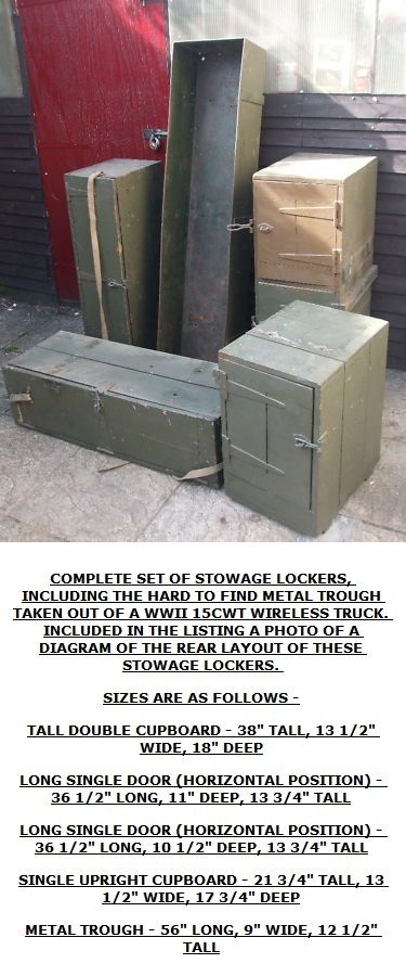 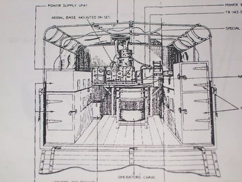 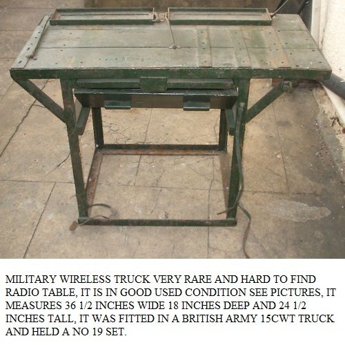 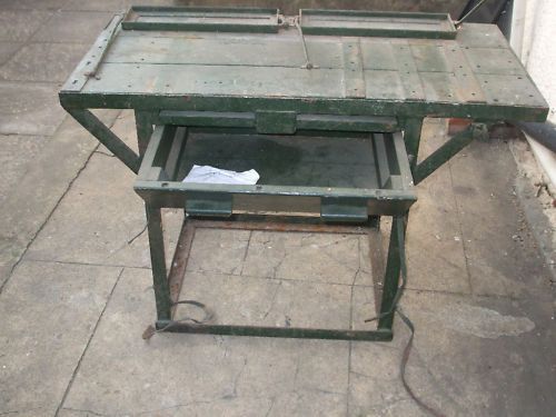 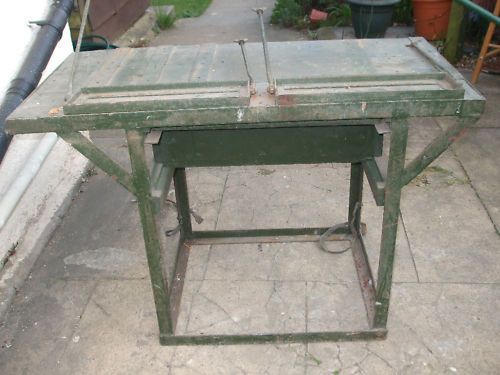 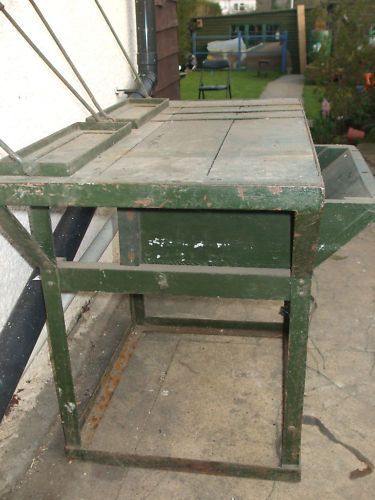   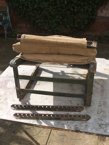 Geoff 
|
|
#2
14-12-15, 17:48
|
|||
|
|||
|
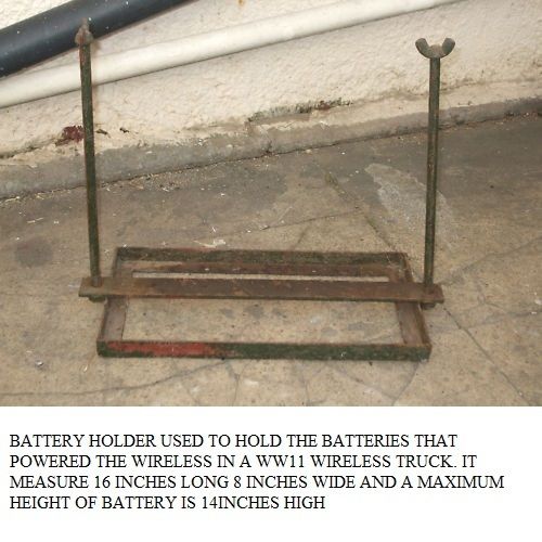
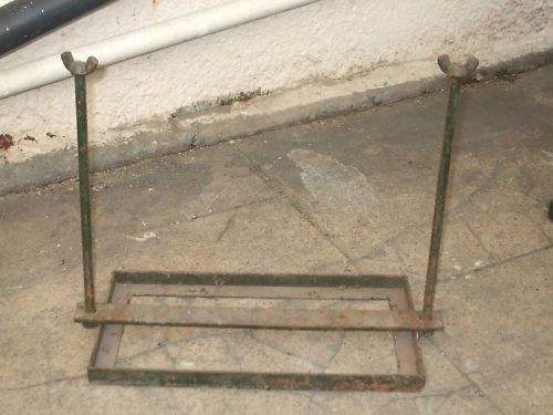
Part 2
     Geoff
|
|
#3
14-12-15, 19:58
|
|||
|
|||
|
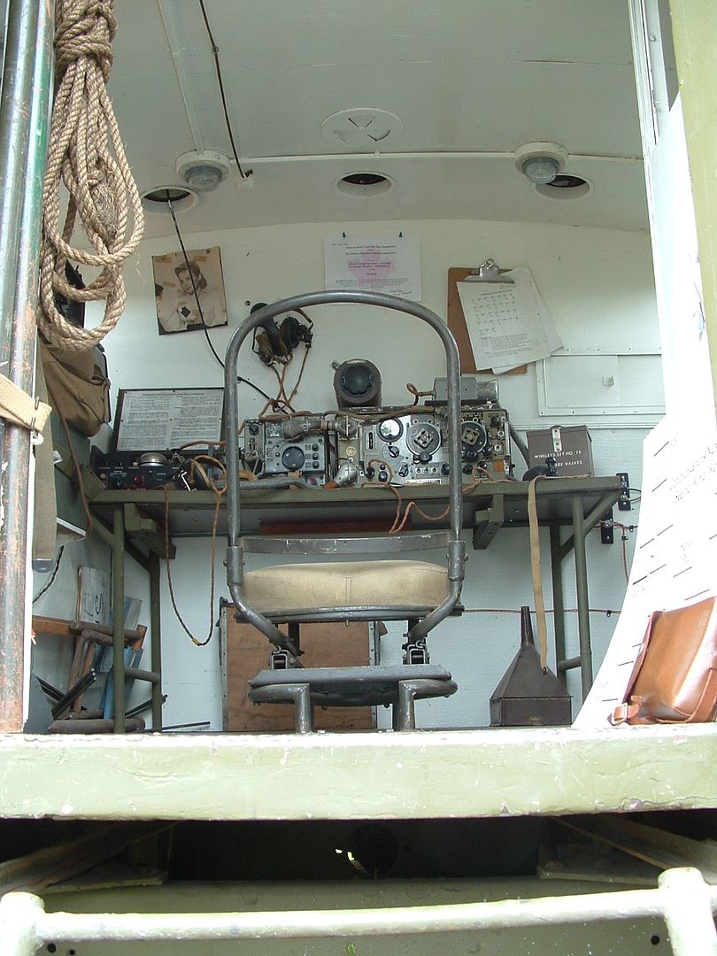
I'll add some photos of the truck in the RCA museum here in Shilo. Perhaps is another truck or two is added to the montage we'll have a concensous on what is by the book and what is fiction.
|
|
#5
14-12-15, 20:14
|
|||
|
|||
|
Hi Guys
Here is the link to some photos taken at CMP 84 http://canadianmilitarypattern.com/CMP84.htm Look at photos 26, 27, 231 and 232 remember to click on the photos in the linked page for full size image. Cheers Phil PS To keep with MLU effort not to have photos get lost I have up loaded the photos below to MLU though the link is still good March 2016.
__________________
Phil Waterman `41 C60L Pattern 12 `42 C60S Radio Pattern 13 `45 HUP http://canadianmilitarypattern.com/ New e-mail Philip@canadianmilitarypattern.com Last edited by Phil Waterman; 14-03-16 at 19:43. Reason: Adding Photos instead of Links
|
|
#6
14-12-15, 22:16
|
|||
|
|||
|
Hi
Photos 1-10 are all the interior for a Bedford MWR in fact they are all the parts i had to make for my truck ,would they have been for sale on E-bay in the UK it seams odd that a truck which has managed to keep its original interior for so many years should be stripped out now ? could the clamps at the back of the wireless table be for more spare battery's ,the normal set up would be two pairs on the floor either side of the wireless table . my first photo shows the restored interior of my truck next photo shows the interior of truck as delivered from the factory Nick
|
|
#7
15-12-15, 03:19
|
||||
|
||||
|
Rob,
I have to visit you in Shilo. Man that is a nice truck. That is the one i will be modelling mine from. Phil, great pictures from a great event, with great collectors . Nice shots from inside the box. Geoff, money shots on the metal wireless table . Great. Wow. 
__________________
44 GPW / 44 C-15-A Cab 13 Wireless 5 with 2K1 box X 2 / 44 U.C. No-2 MKII* / 10 Cwt Cdn Brantford Coach & Body trailer / 94 LSVW / 84 Iltis Last edited by Robert Bergeron; 15-12-15 at 03:27. Reason: spelling
|
|
#8
15-12-15, 03:43
|
||||
|
||||
|
Quote:
__________________
1940 cab 11 C8 1940 Morris-Commercial PU 1941 Morris-Commercial CS8 1940 Chev. 15cwt GS Van ( Aust.) 1942-45 Jeep salad
|
|
#9
15-12-15, 05:01
|
||||
|
||||
|
Gents,
Here is what i was doing today. You collectively answered most of my questions. All the metal shelves should be painted white. What's the consensus on the metal black out curtain holders/frames after seeing the posted pictures by Goeff , Phill and Rob ? Many thanks.
__________________
44 GPW / 44 C-15-A Cab 13 Wireless 5 with 2K1 box X 2 / 44 U.C. No-2 MKII* / 10 Cwt Cdn Brantford Coach & Body trailer / 94 LSVW / 84 Iltis
|
|
#10
15-12-15, 05:01
|
|||
|
|||
|
Thanks for the wonderful pictures of the Shilo model.
?????? in the Shilo model the right inside is different than the Oshawa model.... Oshawa has a bare no 5 charging panel...... is the charging panel covered in the white box in the Shilo model???? Can we have a picture of that white box open???? or the metal cabinet for the chore horse unit. Or is the charging panel part of the metal shelf unit in the RH corner??? Asking all these questions because Grant, from the Barn, will be tackling a radio box in the future and we are very interested in what is what!!!! Cheers
__________________
Bob Carriere....B.T.B C15a Cab 11 Hammond, Ontario Canada
|
|
#11
15-12-15, 05:05
|
||||
|
||||
|
Cheers for Bob Carrière.
Let's see inside that white box and the gen compartment Rob. Please. Good questions Bob. I challenge Grant from the Barn to show his truck in Oshawa right besides mine and the Ontario Regiment's in the near future. Then we could parade them in town. Cheers.
__________________
44 GPW / 44 C-15-A Cab 13 Wireless 5 with 2K1 box X 2 / 44 U.C. No-2 MKII* / 10 Cwt Cdn Brantford Coach & Body trailer / 94 LSVW / 84 Iltis Last edited by Robert Bergeron; 15-12-15 at 05:24.
|
|
#12
15-12-15, 05:16
|
|||
|
|||
|
Factory fresh blackout curtain frames are the same colour as the exterior of the wireless box.
|
|
#13
15-12-15, 05:26
|
||||
|
||||
|
David,
Just like the ones in Rob's pictures ? Army green or whatever then ? ( i do not want to start a discussion about ww2 truck colour )
__________________
44 GPW / 44 C-15-A Cab 13 Wireless 5 with 2K1 box X 2 / 44 U.C. No-2 MKII* / 10 Cwt Cdn Brantford Coach & Body trailer / 94 LSVW / 84 Iltis
|
|
#14
15-12-15, 05:31
|
|||
|
|||
|
First of all, I won't swear to all the interior of the truck being correct. I think it was a base maintenance or a downtown job for the restoration, and there is a little bit of poetic license on the cab and frame of the truck. Hopefullly whomever restored the box made a consensus of the three boxes that were in Shilo. We still have two boxes out in the dustbowl that are untouched but partially stripped. We are not inundated with snow here at this point, so it might be possible for me to go to the dustbowl and snap some shots there as well. Thankfully the wasps and hornets have called it a year.....I seem to get stung in that compound a lot. And if it's not the wasps and hornets, then it is the ample poison ivy that is also in that location.
I'll climb into the back of the van tomorrow and get some shots of that charging panel etc.
|
|
#15
15-12-15, 05:42
|
||||
|
||||
 Man. Man.Thanks. Don't forget the blackout curtain frames..
__________________
44 GPW / 44 C-15-A Cab 13 Wireless 5 with 2K1 box X 2 / 44 U.C. No-2 MKII* / 10 Cwt Cdn Brantford Coach & Body trailer / 94 LSVW / 84 Iltis
|
|
#16
15-12-15, 20:33
|
|||
|
|||
|
Quote:
The radio table with the battery clamp frames on the back is probably for a WS11 because the battery frames look too shallow for an accumulator and are probably for a pair of 250 volt primary battery boxes. The floor mounted battery frames will be identical in size and construction to the ones for the post-WW2 steel cased batteries (because both battery types had to be interchangeable during the changeover period). Batteries used were probably 6V 85AH or 6V 100/125AH, used in pairs. I can look the battery measurements up if required. Chris.
|
|
#18
16-12-15, 00:35
|
||||
|
||||
|
Many thanks Rob.
What is that control module or panel called ? It's part number or description please ? It does not look anything like my Charging Panel C-5 Canadian.
__________________
44 GPW / 44 C-15-A Cab 13 Wireless 5 with 2K1 box X 2 / 44 U.C. No-2 MKII* / 10 Cwt Cdn Brantford Coach & Body trailer / 94 LSVW / 84 Iltis Last edited by Robert Bergeron; 16-12-15 at 02:37.
|
|
#19
16-12-15, 06:41
|
|||
|
|||
|
Is it possible to send me all the Shilo pictures in hi res to my home email address???
That way I can enlarge to my heart's content and make out all the lettering and details. No rush. will send you a PM with the address. Cheers
__________________
Bob Carriere....B.T.B C15a Cab 11 Hammond, Ontario Canada
|
|
#20
16-12-15, 07:16
|
|||
|
|||
|
I may have shrunk them a little too far so I could post them without issue. They are on a DND computer. I know we have issues trying to send and receive photos that are too big on that system, but sure, we can give it a shot. I'll have to figure out what the parameters are.
When I was in the box today I noted a few things that aren't right. For instance, a lot of the conduit is copper plumbing with soldered joints. Not so sure that is correct.
|
|
#21
16-12-15, 16:12
|
|||
|
|||
|
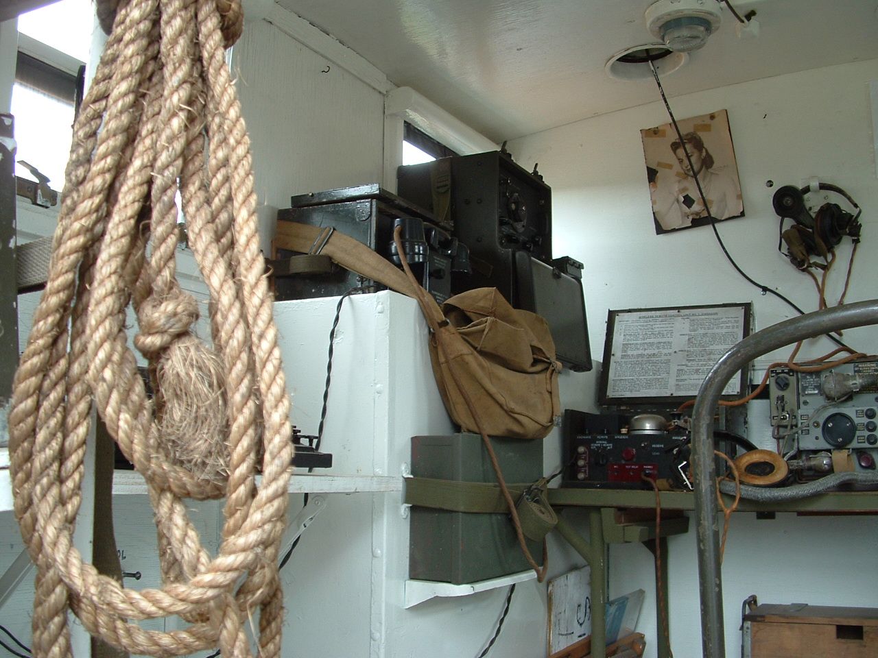
The small white box located on the right side wall between the windows is the Fuse Panel and electrical distribution hub for the interior wiring. A standard piece for all 2K1 and 2K2 Wireless Bodies. On the inside of the lid would have been the Wiring Diagram. The panel inside the fuse box does contain a single selector switch to flip charging current between the two radio battery units, but it is not a charging board per se. The Charging Board with the four selector switches was stored in a rack on the underside of the wireless table when not in use. The large fuses visible in Rob's photo protected the main battery charging circuit. The smaller fuses protected the overhead lighting and power ventilator circuits.
David
|
|
#22
16-12-15, 19:22
|
|||
|
|||
|
Hi David
What was the no 5 charging board used for and when and what was it mounted to for use...... ,,,and if the no 5 board is hard to find where do you even start to look for the proper one switch board that fits inside that box......? Getting korn phused...!!! PS..... and I have seen a copper grounding strap around the wall and the one we have at the barn is an aluminium grounding strap!!!!!
__________________
Bob Carriere....B.T.B C15a Cab 11 Hammond, Ontario Canada
|
|
#23
16-12-15, 20:46
|
|||
|
|||
|
Took me a while to sort out as well, Bob, and I came at it from the opposite direction, finding the fuse box first and assuming it was the charging board. Let a whole whack of No. 5 boards pass by before realizing they were two completely different things and by then the boards had entered the Land of Unobtainium!
What you see in the Fuse Box is a complete, unique package, but does perform a bit of what the Charging Board does. The Charging Board (and if anyone has a manual or working instructions for it, please post in the Wireless Section) was a piece of the kit the wireless team humped into the woods when they went remote with the wireless set, along with a chore horse, two cases of batteries and all the other easy to carry pieces to operate. Not certain of the details of it's operation but suspect it allowed for a number of combinations of power feed to and from the chore horse, batteries sets and wireless all at once, or various controlled patterns as needed. When not needed, it was stored under the bottom of the wireless table: slid into two steel rails. If you look closely at the photos Geoff posted of the wireless table of tubular steel design, that, is an original wireless table for the 2K1 and 2K2 Wireless Bodies. The four legs would end on the floor on triangular steel plates with holes in them to bolt to the floor. Bolts came up from underneath the vehicle and were nutted inside the box. It has been a while and I cannot find my photos of the wireless tables in situ, but if memory serves correctly, on the left side (?) of the table there was a large deep drawer which probably stored the spare parts and valve boxes for the wireless set. Either end of the wide open space under the table had the two flat pressed steel rails the charging board slid into. Under the table Geoff posted, the drawer has been removed and a pair of wooden rails have been added. Backing up to the fuse box again, it worked to control the power distribution and prevent overloads or shorts burning things up, and also allowed flipping the charging current between the two sets of wireless batteries stored in the wooden chests on the floor in the front right corner of the box. In the event a fuse blew, the knife switch allowed the circuits to be disconnected for the fuse change, or any quick trouble shooting, without having to turn off whatever generator was running. I do not believe it allows for running the wireless directly from the generators. Just the batteries. The generator box, which is a bit of a black hole since it is painted entirely green inside, not white or grey, has a set of three switches with a metal guard plate on the side of it that faces the front of the box. The first two are used to start and stop the two generators that have been installed. Remember, the Army installed them, not Wilson Truck Body. It would either be a pair of chore horses or an Onan AC/DC rig on the floor and a chorehorse on the upper shelf in the 'portable' position. The third switch I believe was a 'Mains' switch that isolated any power from getting out of the box. The outside of the gen box door had a large stencil warning the door must be closed and the two outside hatches open for proper ventilation when the generators were running. Green inside the gen box to reduce the visibility factor when those hatches were open. The edges of the gen box that mated up to the plywood walls of the wireless box, along with the perimeter edges meeting the floor, were lined with what appears to be fabric style fender welting to seal for fumes. Not much of that is usually left after things start leaking for decades. Also, where the armour cables exit the side of the gen box, these holes were sealed with a compound that looks a lot like Glazer's Putty. Maybe there is an Electricians version. Soft enough to apply but sets up rock hard. As for the big copper buss bar, Bob, they only ever came copper. Strongly suspect somebody eventually saw dollar signs for all that copper and wogged it, substituting the aluminium you noticed. Hope that helps a bit, Bob. Cheers for now, David
|
|
#24
17-12-15, 00:00
|
|||
|
|||
|
Thanks David
Grant radio box is fiarly complete with the corner box..... some refer to it as the icebox/refrigerator...... and the tube steel table is still in place. However, the ceiling plywood is almost tooching the floor and the walls are also coming off due to water leakage. The Box is now stored inside a dry canvass Winter shelter resting on a spare cab 13 frame. Grant also acquired the disassembled guts of another box...... and I vaguely remember the 3 switches on the icebox...... he has bins of odds and ends which may not start to make sense. Will have to verify if the table has the underneath brackets. He did score a No 5 charging board but I fear we have the wall white box BUT not the innards. I would hate to have to replace the copper grounding bar at the price of copper today. Not sure if the aluminium ground bar is from the spare box or if the good one still has it in place. will try to seak in a peak over the week end and maybe take some pictures. Was there ever a manual for the specific installation of the 19 set in the 2K1 box...? We have yet to start on the restoration of the box. cheers
__________________
Bob Carriere....B.T.B C15a Cab 11 Hammond, Ontario Canada
|
|
#25
17-12-15, 01:06
|
|||
|
|||
|
Dave, I question your theory about the charging board. In 2K1 Wireless I think it mounts on the right side wall between the chorehorse 'fridge' and the switch box. What's under the table is rails for a sliding table and two drawers. The charging board was stored under the wireless table on HUW vans. The interior of the 'fridge' was exterior colour because the chorhorses were meant to be run with the outer sliding doors open (carbon monoxide) and hence cam painted as per the rest of the truck.
Quote:
|
|
#26
17-12-15, 01:11
|
|||
|
|||
|
Bob. I agree a copper bar would be pricey, but possibly doable. Be interesting to cost out what a correct sized piece would be with the appropriate bends in it. The rest is just hole drilling to locate the standoff insulators and the terminal posts. It was copper because of the low electrical resistance it offered. Brass might be just as expensive as copper, or perhaps more so. I personally would not go near aluminium to save my soul after all the negative feedback that surfaced from it's use in home wiring a few years back.
Get yourself a copy of "Wireless Set Canadian No. 19 INSTALLATION INSTRUCTIONS For TRUCK AND GROUND STATION". It was published by Philco in the USA in October 1944 for the Canadian Military and covers everything you need to know about setting up a Mk II or Mk III 19-Set in any of the 2Gx or 2Kx 15-cwt Wireless Trucks and the HUW. There was a flood of these NOS manuals hit the civvy market back in the 1980's and they still pop up from time to time at flea markets and such. One thing I would suggest, with the interior plywood you have still in place is study the hell out of it! Photograph it all until you are ready to scream and measure where all the mounting screws went. It they are original and still there, they are easy to spot: slotted, curved head sheet metal screw about 1/2 to 3/4 inch long, surrounded by a small finishing washer. If you have a second wireless box handy with original plywood still in place you will discover something interesting. The mounting screws for each piece of plywood are all in exactly the same place on each piece. It took me a couple of full Saturdays exploring all the boxes at Princess years ago before that lightbulb went on. Wilson Truck Body was running a full blown assembly line building these boxes with all the related demands for efficient use of hardware and reliable consistency of product. I suspect they took advantage of cabinet maker/custom millwork shops and their equipment to make the pieces of interior plywood. One of the first puzzles I had looking at the interiors was why there was a seam line around the walls at the midpoint half way up. Why didn't they just slap a four foot piece of plywood around the bottom and fill in the upper portion with a smaller strip? Then I noticed the consistent placement of the original hardware on the walls from box to box. Some years later, while working at a local window and door manufacturer, I learned about the amazing machines the millworks industry has available for mass manufacture of large pieces of wood, predrilled for hardware. Think IKEA RTA furniture today. These machines do have size limits for the wood they can handle and back in the 1940's the size limits probably dictated the size of plywood to be worked. So basically, all the pieces of plywood for the insides of these boxes, and all the trim millwork that covered the plywood seams, would have been pre cut and predrilled, ready to be mounted inside the boxes at the appropriate point in the assembly line: speed, efficiency, consistency. I suspect a similar pre drilling process was used with the roof assemblies to ensure all the pieces that had to be mounted on it were in the same place over and over again before they were dropped down on the open box shells. By the way, the trim strip millwork covering the plywood seams is still a standard item at Windsor Plywood and a few other woodworking supply shops around town in these parts. Gotta scoot. There is a snowstorm underway I have to sit and watch. Cheers david
|
|
#27
17-12-15, 01:29
|
|||
|
|||
|
Bruce.
I know the orientation you are referring to. In fact, the manual I mentioned for Bob to track down shows that very layout in one sketch, but there is a problem with the sketch. It does not show the big copper buss bar and the two armoured cable power lines that come off the side of the Gen Box and pass right through that location in the 2Kx boxes. Not at all sure how the 2Gx series of Wireless Boxes looked inside. Never seen one to be honest. The manual text does refer to mounting the Charging Board in that location but it reads rather generic. I do not recall ever seeing the brackets or a shadow of the board on any of the Princess boxes on the walls at that location, however I do have access to two boxes locally I might be able to get to this winter to check out and report back. Anyone got dimensions for the Charging Board No.5 I can reference when I take a boo? David
|
|
#28
20-03-16, 04:33
|
||||
|
||||
|
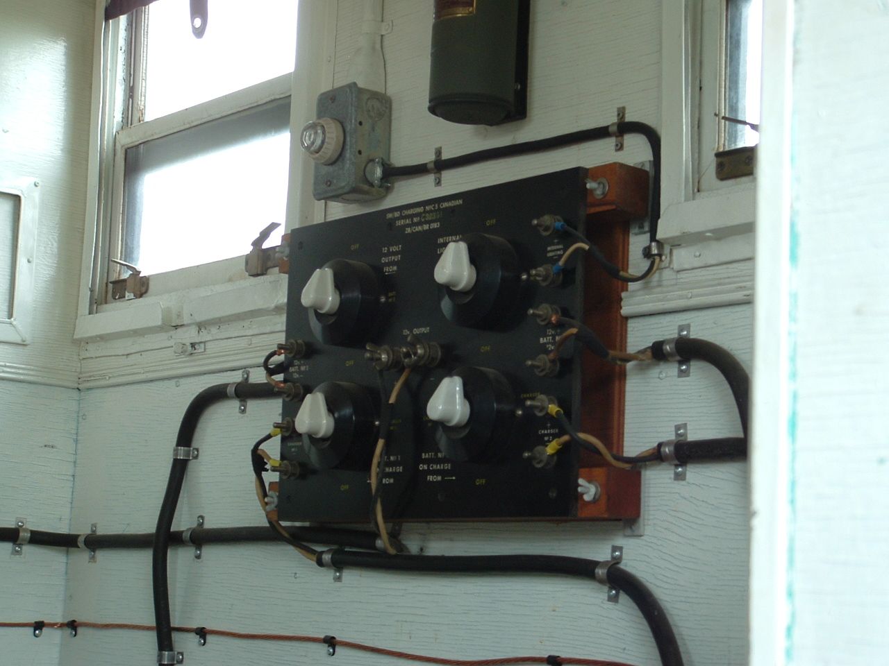
Friends,
Look at this picture closely. There is a switch for internal lighting on the upper right. If it was meant for slogging the chorehorses , batteries and No 19 set out in the woods then why would they need ''internal lighting '' ? This was meant for the inside of the box of a version of Wireless truck for sure. Robert
__________________
44 GPW / 44 C-15-A Cab 13 Wireless 5 with 2K1 box X 2 / 44 U.C. No-2 MKII* / 10 Cwt Cdn Brantford Coach & Body trailer / 94 LSVW / 84 Iltis
|
|
#29
20-03-16, 12:11
|
|||
|
|||
|
Robert
my Bedford MWR has the same charging panel (a British version) and has the same connections for internal lighting which are not used for the interior light in the rear of the truck it has its own rheostat controlled switch located under the wireless table which is supplied from the trucks battery ,could the interior light function on the switch panel be to provide a lighting function when working away from the truck ,i know that WFW shows the charging panel as used to control the power output either from the chore horse generator or the vehicle charging system but the charging panel looks to be of too lighter construction being very breakable and with the exposed wiring on the rear to be dragged into some muddy hole to work as a remote base station . Nicky
|
|
#30
20-03-16, 17:59
|
|||
|
|||
|
Nicholas.
You are very much on the right track. The Charging Boards were a multifunctional item, meant to fill in the gaps and shortcomings on many of the different wireless vehicles in service throughout the war, and at the same time, fill the need for properly float charging wireless batteries when a wireless set was being operated in a 'remote' location. I use quotes around the word remote because the term covers a broad spectrum of locations outside of the wireless truck. Many wireless vehicles in service completely lacked a built in means of properly charging wireless batteries but may have had built in lighting systems. Many lacked even built in lighting and you would most definitely not get built in lighting if you were operating out of a tent in some 'remote' location. So the Charging Board was created. Take the 2K1 and 2K2 15-cwt Wireless Boxes for example. They were the last of the line in the wartime 15-cwt series wireless boxes. By the time they came into production, all the mistakes and shortcomings of the earlier iterations of the 15-cwt wireless box had been taken into consideration. It had it's own interior lighting built in with auto blackout capability. It had a built in float charging system for the wireless batteries. To operate any of this equipment, the Charging Boards were totally, absolutely, positively, redundant. If the wireless equipment has to relocate from the truck to a 'remote' location, then the Charging Board comes into play. As is written on page 45 of the Wireless Set No. 52 manual, when talking about the Charging Board, if it is found that the wireless vehicle in use is already fully equipped for lighting and charging batteries, the Charging Board is stored under the central part of the wireless table. If the wireless vehicle was an older model lacking in either proper battery charging capability and/or interior lighting, the Charging Board was mounted on the wall of the vehicle in a convenient location and became an active part of the working of that vehicle, only being removed if the equipment went 'remote'. The factory wireless table from Wilson that was installed in the 2K1 and 2K2, wireless boxes came equipped with a deep drawer on the left side of the desk. The central and right side belly of the desk was bare. Yes. Absolutely. I have seen a handful of these desks over the years with a long shallow drawer installed under the central part of the desk. Not one of these drawers I have seen matched any of the others. They were all very likely field mods, built locally for whatever reasons. Robert has suggested the Charging Board would be mounted under the rear right side window of the 2K1 and 2K2 Wireless Box. I have never seen signs of one being mounted there after close examination of over four dozen of these boxes. Consider the fact that in that location, two Enfield Rifles are stored along the side wall of the Generator Box for the Wireless Operation and Cypher Clerk. Not a practical place for the Charging Board to be placed with four horking great knobs sticking out from the front of it. David
|
 |
|
|
 Similar Threads
|
||||
| Thread | Thread Starter | Forum | Replies | Last Post |
| Wanted: Wireless table for 2K1 Wireless 5 CMP C-15 truck | Robert Bergeron | For Sale Or Wanted | 6 | 16-12-15 03:55 |
| Wanted: Wireless table for 2K1 Wireless 5 CMP C-15 truck | Robert Bergeron | For Sale Or Wanted | 2 | 23-10-15 20:02 |
| wireless truck 2k1 body | Dennis Gelean (RIP) | The Softskin Forum | 4 | 01-08-09 17:48 |
| C15 Wireless truck | Darrin Wright | The Softskin Forum | 6 | 29-06-07 23:49 |
| Furniture/fittings rear of CMPs | Colin R | The Restoration Forum | 7 | 08-02-07 03:10 |


 Linear Mode

