|
#61
 06-02-11, 14:28
|
|||
|
|||
 Its sunday! My brain goes to sleep on a sunday! thanks a lot will take a look now. cheers! Its sunday! My brain goes to sleep on a sunday! thanks a lot will take a look now. cheers!

|
|
#62
06-02-11, 16:27
|
|||
|
|||
|
I can recommend Alberta too, though I've never had anything made as small as 0.007" wire.........

__________________
Adrian Barrell
|
|
#63
06-02-11, 21:12
|
||||
|
||||
|
I don't know what I was dreaming about there Adrian. I just had a small batch of BSA WM20 fork springs made. They are somewhere near 5/16" wire. I'm not sure if there is a wire gauge but I think there's a 7 in there somewhere?? Ron
|
|
#64
06-02-11, 21:18
|
|||
|
|||
|
It's ok Ron, I thought it was a slip of the keyboard, I couldn't think of a spring on a bike that fine!
__________________
Adrian Barrell
|
|
#65
10-02-11, 22:14
|
|||
|
|||
|
progressof sorts! visited my welder today and he has made some real progress with the welding. Hoping to be able to sandblast the hull within a couple of weeks now
|
|
#66
10-02-11, 22:40
|
||||
|
||||
|
Ah the fun of heavy grinding. Once you've had a spark go into your ear and gotten the little hairs smoldering, you'll forever afterwards keep them trimmed
 Your progress is looking good though.
__________________
David Gordon - MVPA # 15292 '41 Willys MB British Airborne Jeep '42 Excelsior Welbike Mark I '43 BSA Folding Military Bicycle '44 Orme-Evans Airborne Trailer No. 1 Mk. II '44 Airborne 100-Gallon Water Bowser Trailer '44 Jowett Cars 4.2-Inch Towed Mortar '44 Daimler Scout Car Mark II '45 Studebaker M29C Weasel
|
|
#67
10-02-11, 23:01
|
|||
|
|||
|
indeed! I have to admit that it is not me in the photo! His whole workshop is covered in a find grit courtesy of my T16! He doesnt seem to mind too much, hes used to it. This is the guy that "made" the Vickers light tank in the Jaques Liitlefield collection if anyone has seen that. He mainly makes things for councils, like fire escapes, but he has all the equipment and can pretty much do anything if you can motivate him! Like all these clever guys he needs nurturing!! Anyway, really pleased with progress so far.
|
|
#68
10-02-11, 23:10
|
||||
|
||||
|
Quote:
Looks like you must have said the right words to Bud  . Should not be long before you get it back, by looks of it. . Should not be long before you get it back, by looks of it.
__________________
Richard 1943 Bedford QLD lorry - 1941 BSA WM20 m/cycle - 1943 Daimler Scout Car Mk2 Member of MVT, IMPS, MVG of NSW, KVE and AMVCS KVE President & KVE News Editor
|
|
#69
11-02-11, 22:41
|
|||
|
|||
|
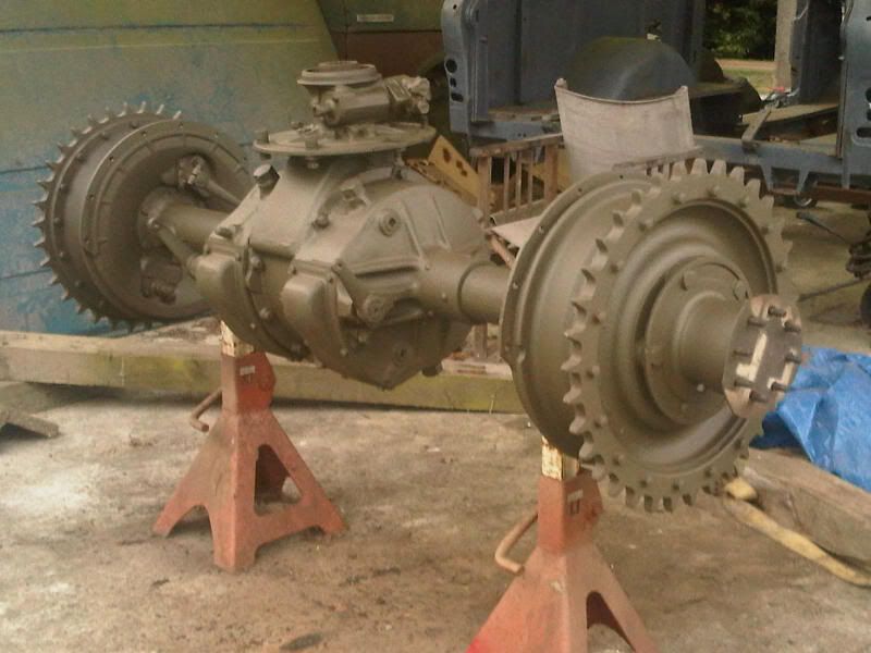
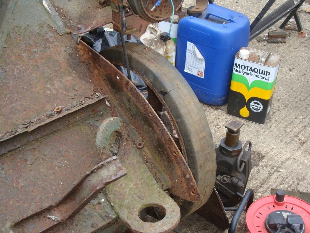
Started on the axle today and found it to be like new inside which is great news. Seems a family of bees got tinto the one brake drum and could nto get out so they were lying inside dead. Other than that, I need to replace a brake shoe as it seems to have broken a few bits off the lining itself but fortunately I have a NOS set of linings. Other than that, it appears to be a matter of cleaning and painting. Surprised how much lighter the axle is without the drums fixed and am thinking of keeping them off until the axle is mounted back in the hull, will certainly be easier to handle.
Last edited by andrew honychurch; 12-02-11 at 09:51.
|
|
#70
02-04-11, 00:46
|
|||
|
|||
|
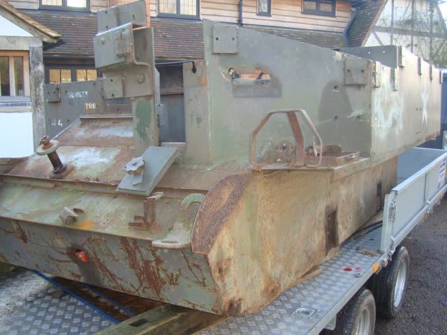
Its been a little while since I posted any updates on the T16, and to be honest its been pretty dull stuff going on. I have now refurbed 3 of the 4 suspension units but the best news was a trip to my metalwork chap today, who has made some real progress. This Carrier had spent a long while in Pounds of Portsmouth scrap yard and like so many had filled up with water which had not done it any good inside, so there was a lot of new metal work to do . This has involved new track guards full length left and right and across the back. Even the bulkhead behind the driver and gunner had rot in it at the bottom and even at elbow height! Anyway, we have now replaced most of this and I have also replaced most of the rotted out drain holes in the floor. This entailed having new rings machined with the correct thread and then letting into the floor where they had rotted out. You can see most of this in the photos, there will need to be quite a bit of making good once it is blasted but I am beginning to feel quite pleased and excited at moving on once again. Hope you enjoy the photos which are not brilliant as they were taken with a blackberry and are not that clear
|
|
#71
02-04-11, 01:16
|
|||
|
|||
|
When you have the hull blasted and painted, and you start bolting bits back on, you will feel great!
__________________
Bluebell Carrier Armoured O.P. No1 Mk3 W. T84991 Carrier Bren No2.Mk.I. NewZealand Railways. NZR.6. Dodge WC55. 37mm Gun Motor Carriage M6 Jeep Mb #135668 So many questions....
|
|
#72
02-04-11, 01:23
|
|||
|
|||
|
indeed I will! The floor inside this T16 is very scabby with rust and I had been worrying about how this was going to come up when blasted. However, I have a little vision of it as the metal worker has to heat up the floor to blow the rust off it and what is left where he has done this is really not too bad! We will see in a few weeks I hope. Still plenty of tin work to do, which is pretty expensive, but I can get busy on making it move back and forwards once more
|
|
#73
02-04-11, 10:58
|
||||
|
||||
|
looking great Andrew...i look at where you are and for some reason all i can hear in my head is the Thompson advert tune "Welcome to my World" hahahaha
Mine is due its first spray now and i know it will be great from that point so Lynn is right there as soon as its clean again.....much better feeling
__________________
is mos redintegro __5th Div___46th Div__ 1942 Ford Universal Carrier No.3 MkI* Lower Hull No. 10131 War Department CT54508 (SOLD) 1944 Ford Universal Carrier MkII* (under restoration). 1944 Morris C8 radio body (under restoration).
|
|
#74
02-04-11, 20:05
|
|||
|
|||
|
thanks Richard, The first spray is always the turning point, suddenly this great lump of rust starts to look like something worthwhile. Dont forget to post up some photos of your Universal when its painted.
|
|
#75
22-04-11, 19:01
|
|||
|
|||
|
what a great day for painting. The UK is bathed in fantastic sun today, and so i took the opportunity to repaint the suspension units and wheels. The first batch of paint that I got was off colour so I got a new batch and I am pretty pleased with it.
So all I need to do is get my hull back and I can get the shop back on the road.
|
|
#76
25-04-11, 19:43
|
|||
|
|||
|
things seem so slow going at the moment, I dont know whether its the hot weather we are having or the lack of the hull for me to be geeting along with, but anyway, I have done half my bogie units now. For some reason I was not looking forward to the job of cleaning all the bearings and seals and washers and putting them all back together. I must be getting overly sensitive to dirty nails in my older age! Anyway, I did two of the units today, taking my time and sitting down for a rest in the sun every now and again.
Its all pretty straight forward, nothing really to be aware off other than trying to line up the hubs, guides bushes and washers so that the axle spindle will go through. In the book they recommend a large spindle sized taper driver which would align everything. Not having one of those I had to use the mark one eyeball but it worked. here are some photos and I have updated the photobucket site as well http://s714.photobucket.com/albums/w...sal%20Carrier/
|
|
#77
30-04-11, 22:16
|
|||
|
|||
|
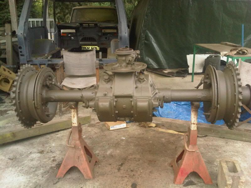
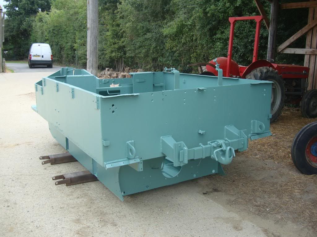
Thats the rear axle complete and ready to refit. That said, its a hell of a weight and wants to dangle with the drive hub down, so it will be a pig of thing to refit without a fork lift which seems the best way to handle it. The T16 also has some shims that fit between the hull side and the axle to set the axle square to the tracks I presume. They look like the may take a bit of lining up as well.
|
|
#78
30-04-11, 23:22
|
||||
|
||||
|
Andrew when you sling it up use a second sling to go around the diff input then when ithas just gone through the hull you can remove the sling and guide it in place. i did my axle on my own with a trolley jack and a block and tackle the block and tackle was used to keep the input part of the diff level. as for the shims i placed them in situ and then picked the holes to line up with a screwdriver you could tack them in place with some silicone sealant if they prove to be troublesome. either way they MUST go back in or you risk causing stress cracks in the lower hull
have fun and watch your toes !!!
__________________
is mos redintegro __5th Div___46th Div__ 1942 Ford Universal Carrier No.3 MkI* Lower Hull No. 10131 War Department CT54508 (SOLD) 1944 Ford Universal Carrier MkII* (under restoration). 1944 Morris C8 radio body (under restoration).
|
|
#79
30-04-11, 23:31
|
||||
|
||||
|
I cheated on mine
 Carried the parts up the hill one at time and bolted them onto the vehicle as I went. Most of it was manageable but the planetary gears weigh a ton. Carried the parts up the hill one at time and bolted them onto the vehicle as I went. Most of it was manageable but the planetary gears weigh a ton.You can tap the spacers or shim plates between the hull and the brake plates once you know the final drive center is bolted up properly. I think they were designed to allow easier fitting of the unit onto the hull at production. That way minor variance in the welded body panels wouldn't cause issues when everything was going together.
__________________
David Gordon - MVPA # 15292 '41 Willys MB British Airborne Jeep '42 Excelsior Welbike Mark I '43 BSA Folding Military Bicycle '44 Orme-Evans Airborne Trailer No. 1 Mk. II '44 Airborne 100-Gallon Water Bowser Trailer '44 Jowett Cars 4.2-Inch Towed Mortar '44 Daimler Scout Car Mark II '45 Studebaker M29C Weasel
|
|
#80
30-04-11, 23:49
|
|||
|
|||
|
Thanks Guys. I was thinking of using a sling but to be honest, my Engine crane only just lifted the axle. I assume its a fair bit heavier than a standard Universal, presumably because of the added differential steering mechanisms. Just lifting a brake drum proved to be a right old weight. Mind you I am probably just getting old!
Its interesting what you say about fitting the axle before the shims, which would make sense, so lets hope there is a bit of lee way when refitting. I will be watching my toes Richard..this thing could seriously damge you if it fell on you. Anyone know the weight?
|
|
#81
10-05-11, 20:32
|
|||
|
|||
|
I just want to post a thankyou to a few of you guys out there. I have received serious help from David Gordon who as we all know has restored his T16 to what must be the yardstick
 for all of us to measure our efforts by. Unbeliveable. Also, I have been kindly sent a spring all the way from NZ by Lynn Eades to complete my suspension. I cannot believe that you guys will put yourself out so much to help others. And Marc Van Aalderen has kindly sourced, collected and posted me a drive coupling gear from Holland. I know all of us will have such tales of help, assistance and comraderie but I just had to mention it. Its a great hobby and this webforum is terrific. Thanks to all of you who make it what it is. for all of us to measure our efforts by. Unbeliveable. Also, I have been kindly sent a spring all the way from NZ by Lynn Eades to complete my suspension. I cannot believe that you guys will put yourself out so much to help others. And Marc Van Aalderen has kindly sourced, collected and posted me a drive coupling gear from Holland. I know all of us will have such tales of help, assistance and comraderie but I just had to mention it. Its a great hobby and this webforum is terrific. Thanks to all of you who make it what it is.
|
|
#82
10-05-11, 22:32
|
||||
|
||||
|
It is a rarity in the MV fraternity but here in Carrier land we share the love
always good to hear when good deeds are being done.
__________________
is mos redintegro __5th Div___46th Div__ 1942 Ford Universal Carrier No.3 MkI* Lower Hull No. 10131 War Department CT54508 (SOLD) 1944 Ford Universal Carrier MkII* (under restoration). 1944 Morris C8 radio body (under restoration).
|
|
#83
15-05-11, 20:52
|
|||
|
|||
|
Picked up my new fabricated tool boxes this week. Really pleased with them, just need to paint them nicely and get the hull back. Decided to start with the instrument panel as well. Had a bit of tin worm in the corner, but with my new bender it was a cinch. Nice to find something goes according to plan for once. If anyone has a T16 dashpanel light, similar to UC but slightly different, and wants to sell it please let me know. Also, looking for a new voltage divider which fits in the dashpanel. Any help much appreciated .
|
|
#84
01-06-11, 18:30
|
|||
|
|||
|
I am struggling a bit with the fabrication of the front wings for the T16 right now. If anyone out there can help I would be very grateful. The problem is that there is a curvature up in the front wing to encompass the front idler wheel. what I had on my T16 was incorrect having been changed years ago , and now I cannot really work out how it all fits together. There is a small fixed part of the fender which is horizontal and welded to the hull. I know the length and width of this , but where the problem that I think this may kick upwards towards the front of the vehicle, just where the detachable front fender bolts to it. If I dont get this correct I will not get the kick up right. Can anyone help please?
  if this works it will illustrate the kick up, but how that is arranged I cannot tell from my T16.
|
|
#85
01-06-11, 18:42
|
|||
|
|||
|
here is another photo which may illustrate what I am talking about
|
|
#86
01-06-11, 19:14
|
||||
|
||||
|
Not really sure how to measure or even accurately describe that curve. It is very minor though. The removable curved fender bolts on top of the flat extensions over the tracks. But it drops down below the height where the two parts come together. Likely something to serve as a reinforcement since it amounts to about two thicknesses of the metal. The swoop up towards the center of the fenders is roughly 2-3 more thicknesses of the metal in height above the bolt together location. So the slight dip, followed by the upswing makes it seem so pronounced.
If you still have the left and right vertical metal sections on the hull that the fender bolts onto, that should serve as a guide. The bolt holes are uniform in spacing, along with how the fender seats on it.
__________________
David Gordon - MVPA # 15292 '41 Willys MB British Airborne Jeep '42 Excelsior Welbike Mark I '43 BSA Folding Military Bicycle '44 Orme-Evans Airborne Trailer No. 1 Mk. II '44 Airborne 100-Gallon Water Bowser Trailer '44 Jowett Cars 4.2-Inch Towed Mortar '44 Daimler Scout Car Mark II '45 Studebaker M29C Weasel
|
|
#87
02-06-11, 07:48
|
|||
|
|||
|
Thanks David. I think my problem is that what I thought were the original vertical "inner fender" are in fact incorrect. This is throwing out my curvature calculations. The vertical plate should, I think, have a recessed edge for the fender to fit down against. here is mine, which I am sure is incorrect.
|
|
#88
14-07-11, 20:08
|
|||
|
|||
|
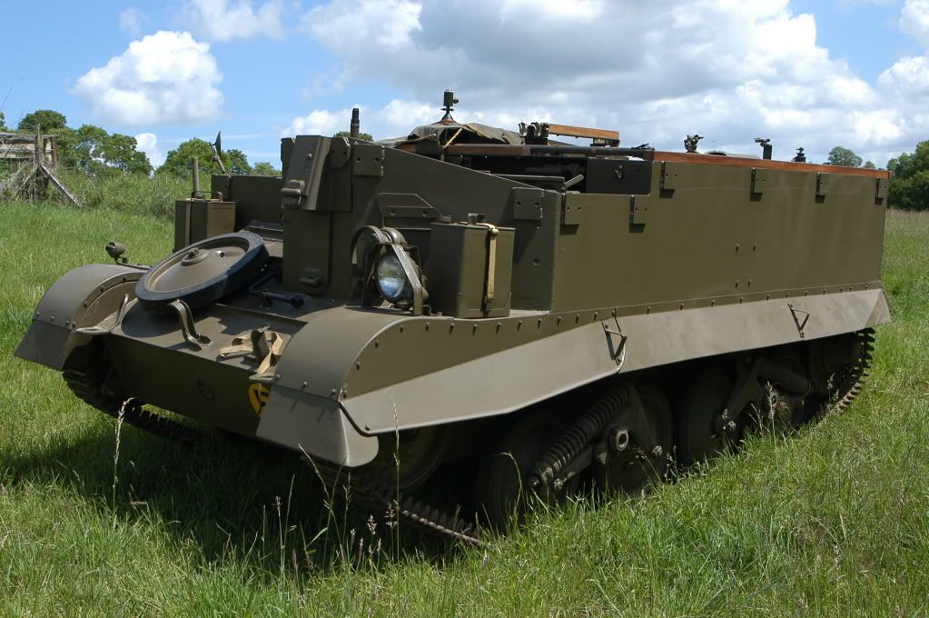
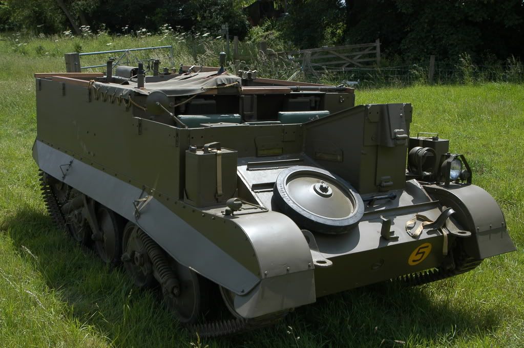
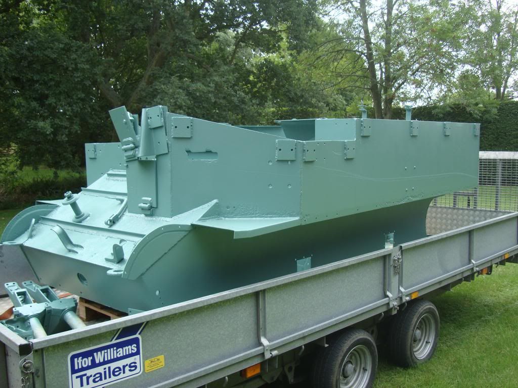
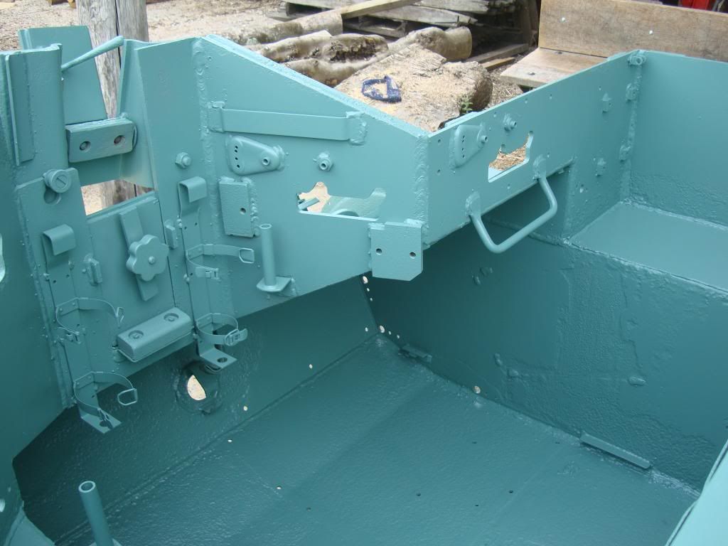
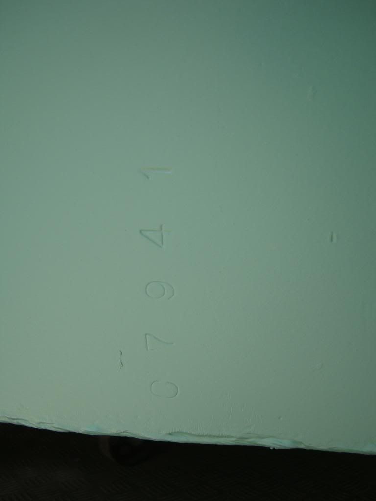
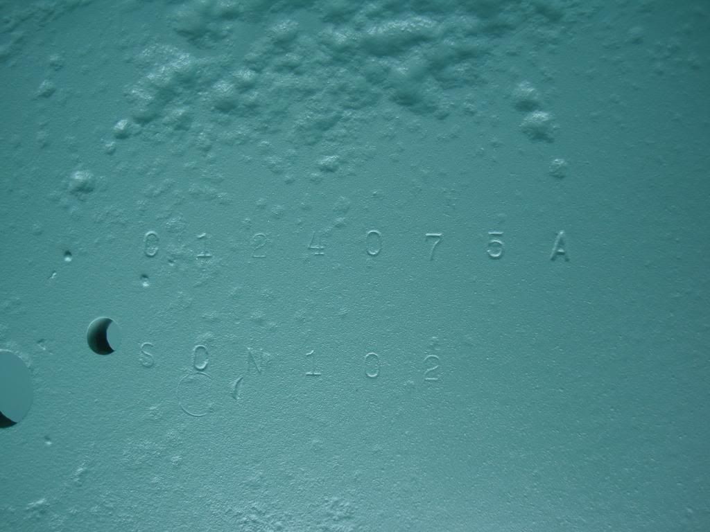
After what seems an eternity, today I collected the T16 from the sandblasters! Wow, its soooo clean! I hardly dare stand on it for fear of making it dirty. There are no horror stories thankfully, we addressed most of those when welding up the nasty bits. I can really feel we are past half way now, especially as I have already completed a lot of the parts to fit back on. I am going to spend some time filling some of the worst of the pitting, really to make it look a bit better. I realise some will view this as a waste of time, but if I can improve the worst bits I think it s worthwhile. Lots of data stamps on the panels exposed by the blasting. Does anyone know whether any of these are actual serial numbers?
|
|
#89
14-07-11, 20:53
|
|||
|
|||
|
the hull looks really smart, a good place to start the restoration proper. with regard to the numbers stamped on the armour i think they may be the part numbers for that particular piece of plate, my carrier has the same kind of thing but that is only an educated guess.
all the best rick
__________________
_______________________ 1941 mk1 mortar Carrier 1941 Mk1* Carrier 1942 Mk1* Carrier 1943 T16 Carrier 1945 Mk3 Dingo 1941 Mk3 Covenanter 1941 Mk4 Churchill AVRE (now sold) 1944 Mk6 Cromwell (now sold) 1952 Mk3 Centurion 1952 ARV Centurion 1952 ARV Centurion 1953 Mk3 Centurion (breaking)
|
|
#90
15-07-11, 02:06
|
||||
|
||||
|
Looks like they did a great job. You'll suddenly be measuring progress in leaps now that the welding and stripping tasks are finished.
Noticed your hull was drilled for both the 4-inch smoke discharger on the gunner side and a 2-inch mortar mount for throwing smoke in the forward gunner area. Both were used throughout the war but I'd always thought vehicles were drilled for one or the other. Sure there is some history there with it having been in service and then reworked later on. One thing I've seen on a lot of T-16s are the grouping of four bolts in the center of the side armor just over the tracks. I've never known what would have been there as nothing is documented in the manuals. Had to have been a British modification/addition of something. Anyone know?
__________________
David Gordon - MVPA # 15292 '41 Willys MB British Airborne Jeep '42 Excelsior Welbike Mark I '43 BSA Folding Military Bicycle '44 Orme-Evans Airborne Trailer No. 1 Mk. II '44 Airborne 100-Gallon Water Bowser Trailer '44 Jowett Cars 4.2-Inch Towed Mortar '44 Daimler Scout Car Mark II '45 Studebaker M29C Weasel
|
 |
|
|


 Linear Mode

