|
#31
 14-05-09, 11:36
|
||||
|
||||
|
great stuff ! looks really good
__________________
is mos redintegro __5th Div___46th Div__ 1942 Ford Universal Carrier No.3 MkI* Lower Hull No. 10131 War Department CT54508 (SOLD) 1944 Ford Universal Carrier MkII* (under restoration). 1944 Morris C8 radio body (under restoration). 
|
|
#33
14-05-09, 17:51
|
||||
|
||||
|
i take it that part of the sprocket faces in towards the hull ? and the second set of teeth will fit into the middle lugs on the tracks ?
__________________
is mos redintegro __5th Div___46th Div__ 1942 Ford Universal Carrier No.3 MkI* Lower Hull No. 10131 War Department CT54508 (SOLD) 1944 Ford Universal Carrier MkII* (under restoration). 1944 Morris C8 radio body (under restoration).
|
|
#34
15-05-09, 03:43
|
||||
|
||||
|
Update:
Well the work continues, Here I have added the rear sprockets and gearboxes. The gearboxes are barely noticeable. I'll be adding extensions to the back side of the sprockets to give them the width. Here are the latest pics with the gearboxes and sprockets added to the hull 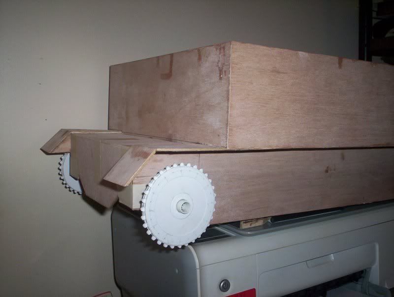 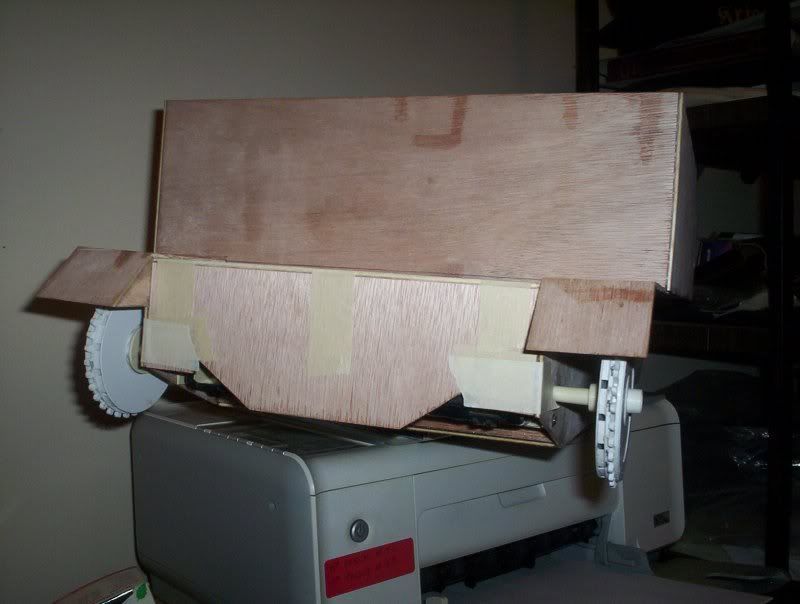 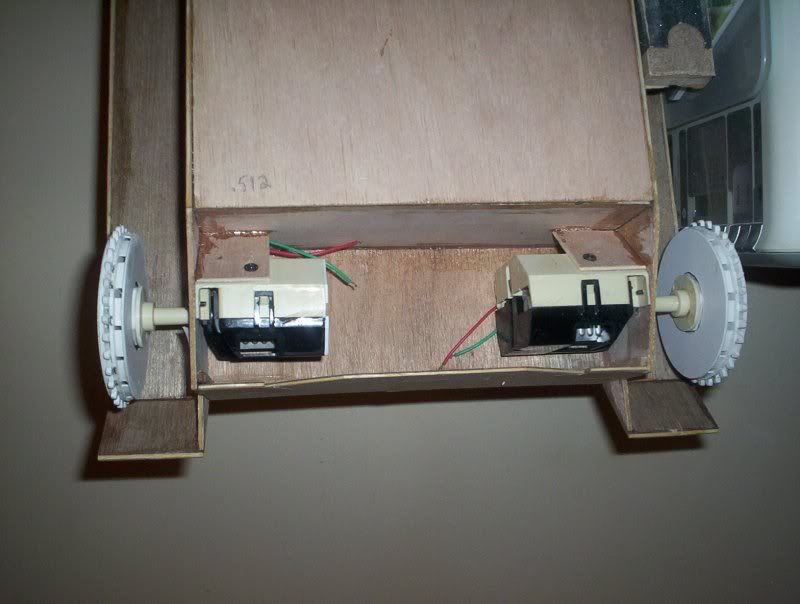 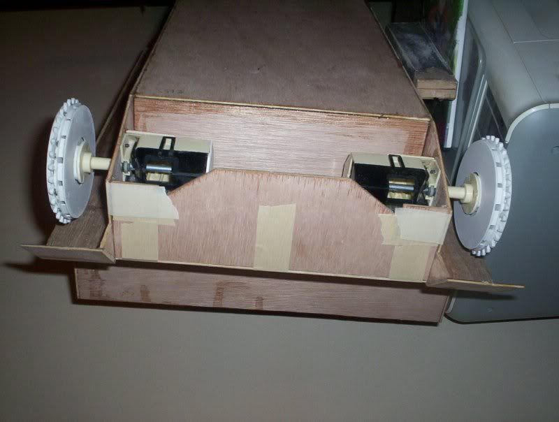
|
|
#36
17-05-09, 03:59
|
||||
|
||||
|
Harold, what a great job you are doing (although obsessive comes to mind). ;o)
__________________
Those who live by the sword will be shot by those of us who have progressed. - M38A1, 67-07800, ex LETE
|
|
#39
17-05-09, 15:10
|
||||
|
||||
|
I did a google search on the specifications of the carriers and get several different clearance measurments from 8" to 11" what you posted Ron so maybe I should divide the difference and go with something in the middle. Here's one reference link I found if it's of any interest to anyone... http://www.wwiiequipment.com/index.p...iers&Itemid=55
|
|
#41
17-05-09, 17:53
|
||||
|
||||
|
yeah spec sheet says 8" ground clearence for British and Canadian units, not sure about the Australian carriers.
__________________
is mos redintegro __5th Div___46th Div__ 1942 Ford Universal Carrier No.3 MkI* Lower Hull No. 10131 War Department CT54508 (SOLD) 1944 Ford Universal Carrier MkII* (under restoration). 1944 Morris C8 radio body (under restoration).
|
|
#43
17-05-09, 22:30
|
||||
|
||||
|
my mistake Ron, but I always thought ground clearance was this measurement ie the point in which the hull would ground out. Page 118 in vol.1 of the carrier book shows the measurement from the bottom of the hull ( at the right angle bar that protects the exhaust pipes under the hull) to the ground as being 8" unless i missunderstand its meaning which is very easily possible with my meager brain pan
 (PZRwest you want to get these books from Nigel Watson mate absolutely fantastic with more reference shots and schematics than you can shake a track link at !  ) )
__________________
is mos redintegro __5th Div___46th Div__ 1942 Ford Universal Carrier No.3 MkI* Lower Hull No. 10131 War Department CT54508 (SOLD) 1944 Ford Universal Carrier MkII* (under restoration). 1944 Morris C8 radio body (under restoration).
|
|
#45
18-05-09, 02:11
|
||||
|
||||
|
Update:
Now I have the rear drive sprocket made I turned my attention to the rear road wheels and rear suspension units. For springs I went to my local dollar store and picked up 8 dart guns and removed the springs from them. The metal rods are just coathanger wire with the nuts from old video and audio card soldered on the ends. When finished a nut will be soldered to the opposite ends as well. Here are a couple pics of the 2 suspension units. One assembled and one just the componants. When these are finished I will move onto the front units 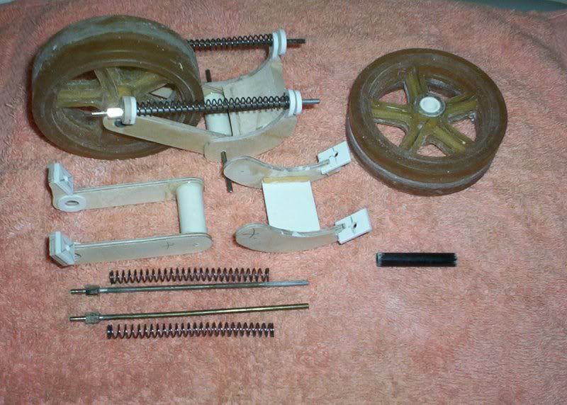 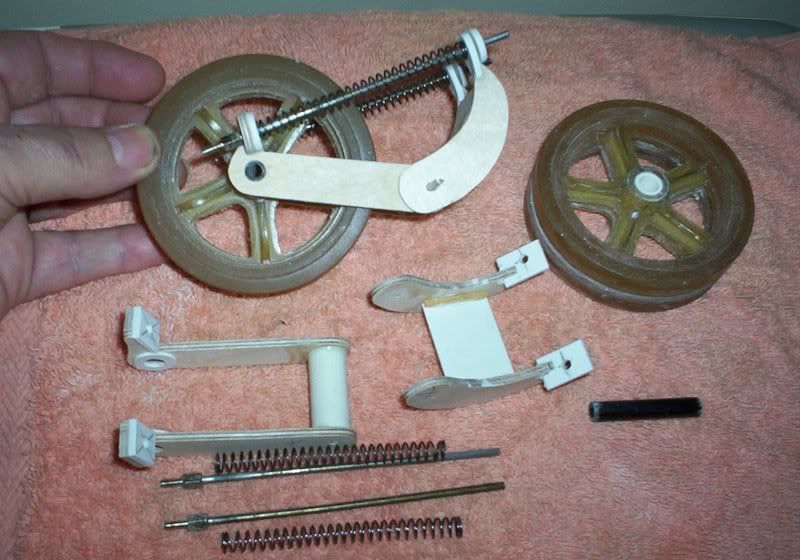
|
|
#46
18-05-09, 05:54
|
|||
|
|||
|
Hi, is all this work going to build a 1/6th scale model bren carrier just templates until the real build? Very Nice job on the wheel assemblys and the spring and fork parts. It would be really cool if you could cast the fork assembly from lead and the Hull and frame made
 from sheet steel. but the lighter the model the more fun it is carrying her around. Regards Aidan from sheet steel. but the lighter the model the more fun it is carrying her around. Regards Aidan
|
|
#47
20-05-09, 04:03
|
||||
|
||||
|
This carrier will be my carrier. I made card stock templates of the hull and suspension pieces so I can make another one in the future.
Update: Work continues. Here I have made the front road wheel suspension system, and temporarily mounted the track and suspension parts to the hull. 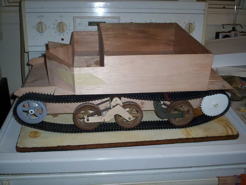 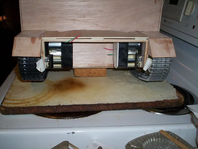  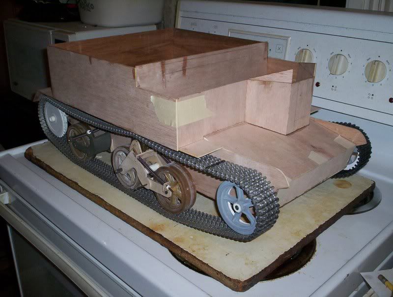 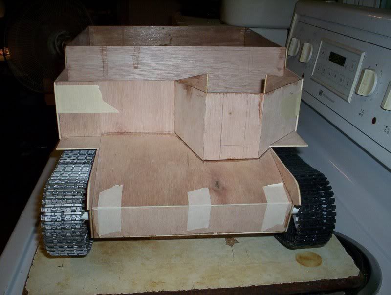
|
|
#48
20-05-09, 11:53
|
||||
|
||||
|
seriously cool ! how long do you think the sprockets will last ? wonder if you could make an IC version ? would need some sort of diff assembly though.
__________________
is mos redintegro __5th Div___46th Div__ 1942 Ford Universal Carrier No.3 MkI* Lower Hull No. 10131 War Department CT54508 (SOLD) 1944 Ford Universal Carrier MkII* (under restoration). 1944 Morris C8 radio body (under restoration).
|
|
#50
20-05-09, 16:07
|
||||
|
||||
|
sorry rather than it being powered by electric motors you could use a 4 stroke engine out of a model plane, i have a large scale P47 which uses a 4 stroke and she sounds amazing on full throttle. IC being "internal combustion"
__________________
is mos redintegro __5th Div___46th Div__ 1942 Ford Universal Carrier No.3 MkI* Lower Hull No. 10131 War Department CT54508 (SOLD) 1944 Ford Universal Carrier MkII* (under restoration). 1944 Morris C8 radio body (under restoration).
|
|
#51
20-05-09, 17:43
|
||||
|
||||
|
No I won't be useing a fuel powered engine in it. It is very light so the electric motors/gearboxes should handle this carrier quite well. There are sound moduals that can be used and one can record engine sounds and use them.
|
|
#52
20-05-09, 18:53
|
||||
|
||||
|
awesome ! its looking great cant wait to see it all painted up.
__________________
is mos redintegro __5th Div___46th Div__ 1942 Ford Universal Carrier No.3 MkI* Lower Hull No. 10131 War Department CT54508 (SOLD) 1944 Ford Universal Carrier MkII* (under restoration). 1944 Morris C8 radio body (under restoration).
|
|
#53
21-05-09, 03:13
|
||||
|
||||
|
Well curiousity got the best of me and just had to see how the carrier ran on rc so I used the spare radio gear for an HL rc tank. I added my regiments marching song called I'm Ninety-Five. For the first test run it doesn't run too bad. Here's the video.
PS you will see one good reason for doing up the chin strap on your helmet.... LOL 
|
|
#54
21-05-09, 17:54
|
||||
|
||||
|
excelent ! once you get the center engine compartment in you may even be able to fit the sound and smoke module in there. love the suspension ! any chance of some close up video of it going over something on a desktop to show the suspension at work ? I would love a kit of this so i could tear down that spare tiger i have (which is spare parts for Nathans tiger) so i could build one too.
__________________
is mos redintegro __5th Div___46th Div__ 1942 Ford Universal Carrier No.3 MkI* Lower Hull No. 10131 War Department CT54508 (SOLD) 1944 Ford Universal Carrier MkII* (under restoration). 1944 Morris C8 radio body (under restoration).
|
|
#55
27-05-09, 06:49
|
||||
|
||||
|
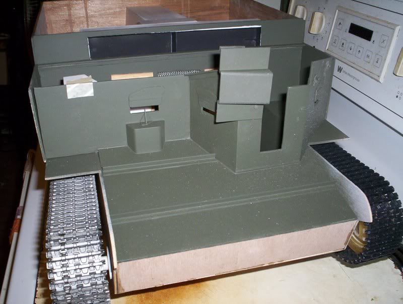
Update:
I decided to remove the 5-spoked road wheels and idlers and replace them with the 6-spoked wheels. I have sealed, sanded, and primed the front top glacis and temporarily added the upper shield. I opened up the openings in the divider between the drivers compatment and the rear compartment. I also added more tension to the rear suspension so it sits level now... and the work continues. Here are the latest pics 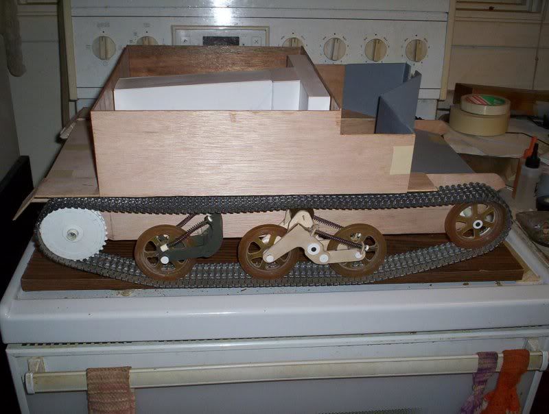 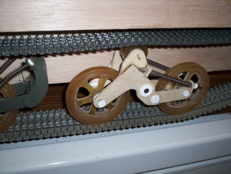 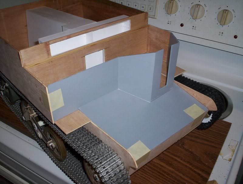 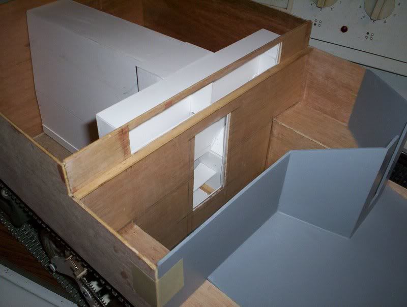 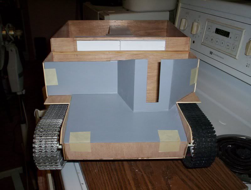 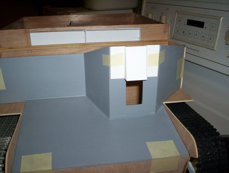 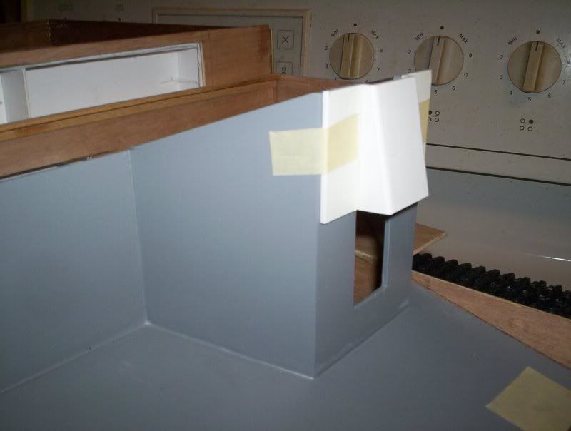 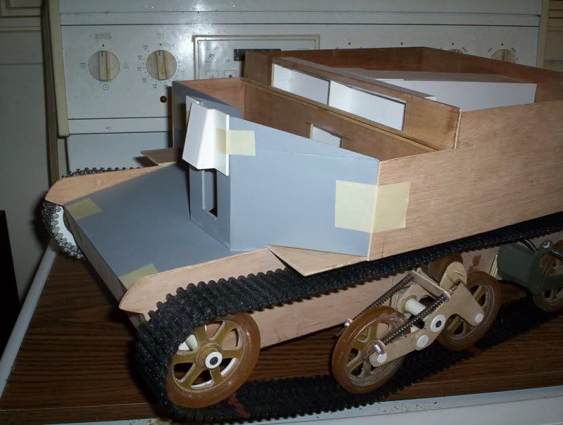
|
|
#56
28-05-09, 06:05
|
|||
|
|||
|
This is a nice model, congratulations on your very rapid build. The tracks you chose look very suitable for the scale, too. Presumably you are steering it by switching the motors, but I'm curious - are you going to implement track warping too? Your last photo above seems to show the centre bogie assembly in a slidable tube. By the way, a popular and very cheap drive unit for large scale tanks are cordless screwdrivers. They have very compact dual-stage planetary gearboxes with heaps of torque.
Steve.
|
|
#57
04-06-09, 05:44
|
||||
|
||||
|
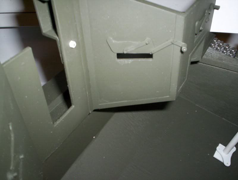
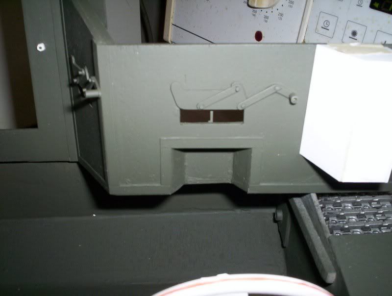
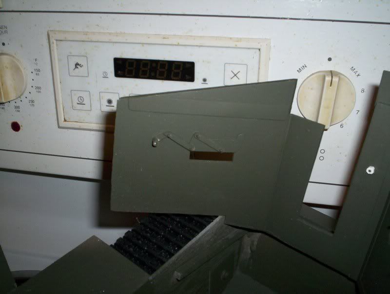
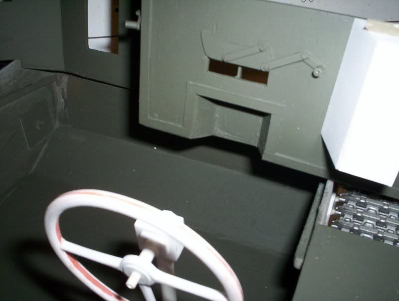
Update... lots of pics:
Well work is progressing on the carrier. I have opened up the upper vent and the radiator openings in the bulkhead. I used a piece of aluminum screening as a mock rad grill. I have added vision ports and guards with actuateing levers, constructed the steering wheel and mast, temporarily attached the seats, added dummy hinges to the ports side upper shield, made the front upper shield moveable, started the instrument cluster compartment. Here are pics of the work so far... there are lots of them 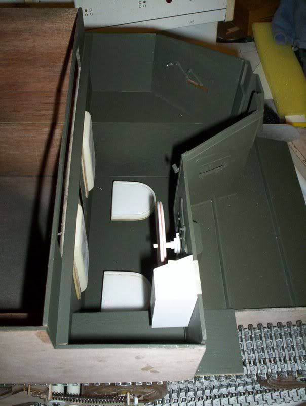 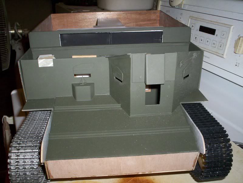 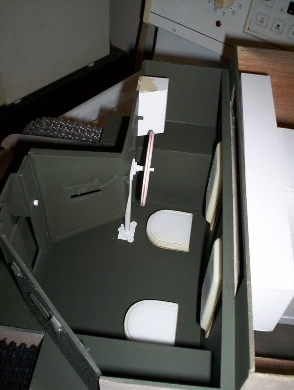 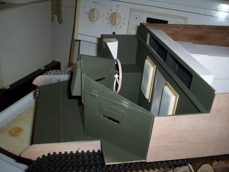 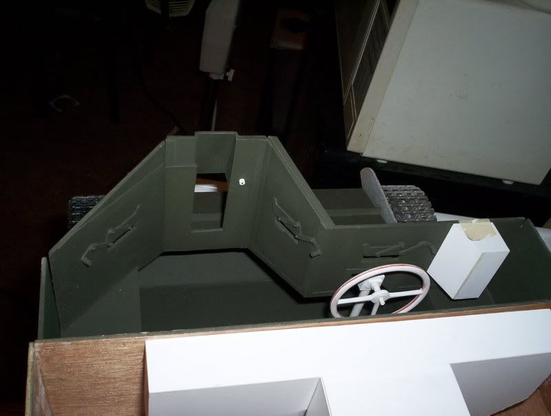 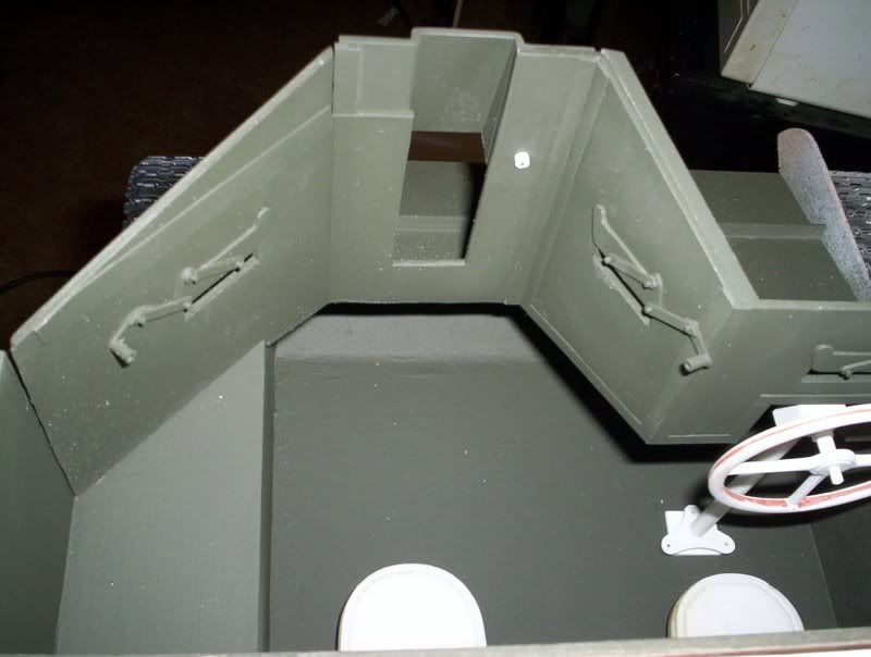 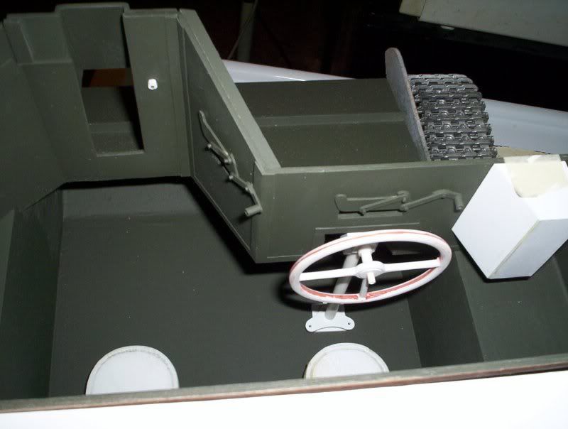 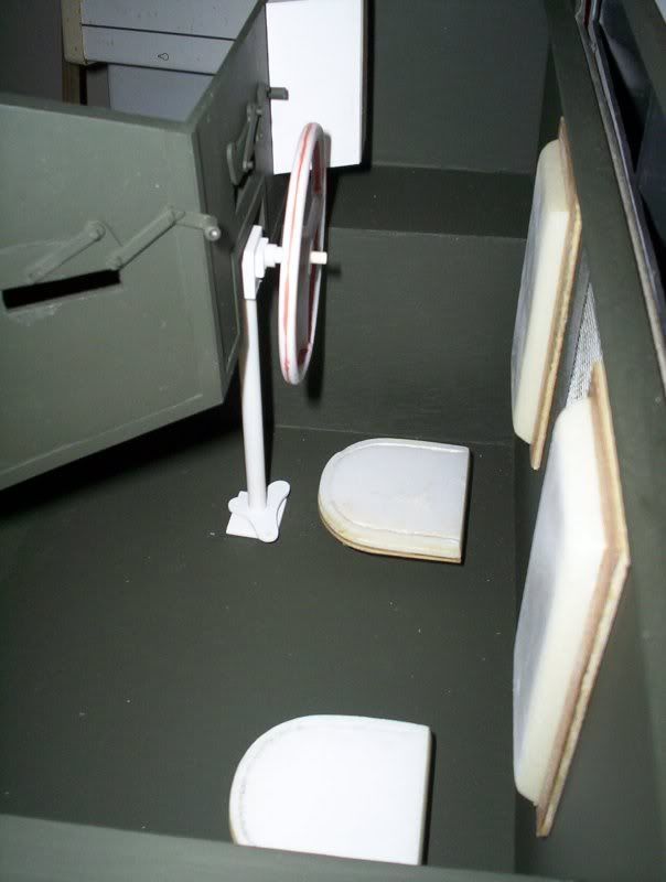 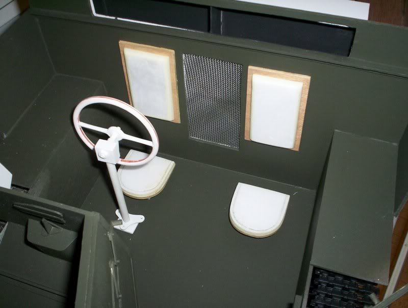 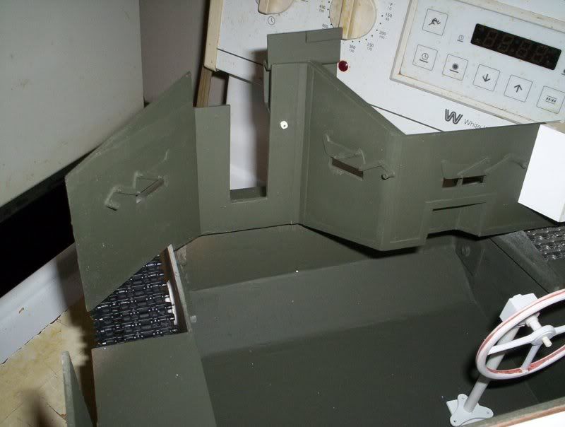
|
|
#60
04-06-09, 10:21
|
||||
|
||||
|
Quote:
classic love it !!!its looking good Harold, cant wait to see the finished article Rich
__________________
is mos redintegro __5th Div___46th Div__ 1942 Ford Universal Carrier No.3 MkI* Lower Hull No. 10131 War Department CT54508 (SOLD) 1944 Ford Universal Carrier MkII* (under restoration). 1944 Morris C8 radio body (under restoration).
|
 |
|
|


 Ron
Ron

 Linear Mode

