|
#1
 30-11-10, 15:27
|
||||
|
||||
|
I have recently joined the forum, albeit do frequent the hmvf here in old Blighty.
Thought that I would post some pics of the Pig I have aquired and will be starting restoration on soon. That is once I have the Lightweight and Rover 8 a bit more advanced. However the PIG may sneek in front  Please follow the thread http://hmvf.co.uk/forumvb/showthread...er-Pig-Origins The damage is essentially external and concentrated around the wings and lockers etc. It would be great to share other members experiences on the wing/ locker rebuilds. In particular if any drawings exist. I intend to survey mine and then produce some fabrication drawings in AutoCAD for replication etc. Believed to be ex 4th Guards Brigade. ERM is 13BK33. Would just like to say a big thank you to Clive Elliott for his assistance to date. Who has confirmed the following from his archives and database. Chassis Serial No.21333 ERM 13 BK 33 FV1601(A) Engine No.6190 Contract No. 6/VEH/27455 Date in service 4/12/53 Delivered to 31st ‘B’ Vehicle Depot Church Broughton Receipt Voucher No. CBR/R/4454 Converted to FV1611(A) 1959-60 Struck off 9/8/67 OSDD Ruddington Sale No. 93 Lot No. 718 Sale price £40
__________________
Wayne 1959 Royal Ordnance FV1611A Last edited by FV1611A; 01-12-10 at 00:41. Reason: added content 
|
|
#2
04-12-10, 00:52
|
||||
|
||||
|
Quote:
So I initially made a mock-up out of ply & cardboard, then had the main outer panel cut for me. The problem was that trying to cut sides & fit them to together as a rigid structure was very difficult. I wanted to carry some heavyish tools in the lockers & needed some rigidity on which to construct the lockers. I have no skills or facilities for sheet metal work so it had to grow on a frame. Once I was happy with the geometry of the frame then the locker could grow from that. The precut side was inexplicably too long in one area & too short in another. In the end I fixed the panels on & then cut them to shape. I was helped by seeing on photos that the rear panel was bolted on & implied some sturdiness underneath. I realise on your production Pig that the locker is longer & has a fold down side. There is one of those here & I think a matching side panel is in a lock up in Reading   
__________________
Clive Elliott GW4MBS (Old) South Wales UK
|
|
#3
08-12-10, 15:20
|
||||
|
||||
|
Clive
That is indeed helpful and thank you for sharing the images. I must admit that the idea of a pre-fabricated arrangement being offered up for attaching would make the most sense following the making of templates in cardboard/ thin plywood etc. What was the actual design criteria for these lockers/ bins as there are quite a few. What would the vehicle have used them for. You mention your carrying tools etc. Would they have been used for CES items? What thickness/ gauge of steel did you use and what it the same thickness as the original panels would have been? The rear /side/ top lockers are different to yours and I do remember one of the longer panels being at Casa Clive last time I visited. You did also have front wing/ mudguard panels from memory for one side. Was that correct. In hindsight now I would like to purchase those so can they be set aside for when I collect the filter and headlights next time. It is interesting to see your FV1609 in such a condition of work in progress especially as it looks so resplendant now. She's a credit to your hard work. Have a beer on me for all your continued support. Much appreciated. 
__________________
Wayne 1959 Royal Ordnance FV1611A Last edited by FV1611A; 08-12-10 at 15:47. Reason: added content
|
|
#4
09-12-10, 01:43
|
||||
|
||||
|
Wayne here is the drawing made for cutting the main side. Obviously different for a FV1609 from a FV1611. As you will appreciate it is difficult take measurements for something that is in thin air. The net result was errors of an inch or so as something wasn't right with the angles, giving a deficiency one end & surplus the other
 The result was to build the frame & feel happy with that then to cover it & cut it down to shape. Without the skill or equipment to spot-weld & I had no MIG at the time, I cheated by fixing the outer sheet to the wheel arch with countersunk rivets which were eventually smoothed over with filler. I just didn't want to risk melting through or buckling the thin sheet.  Given my propensity for reversing the Pig into various obstructions, the lockers on a frame have proved more durable & easier to repair than a more authentic series of flimsy sheets held together with spot-welds. Yes various bits of CES & other kit could go in the lockers, no specific space allocations. Unless you keep it under cover from the rain there isn't too much you would want to store in there given the points of entry for water & worse on yours as you have another hinge. Incidentally the picture of it in red oxide, the top lockers hasps were just from B&Q & are surprisingly close to what was originally fitted. The small side locker is original with its original hasp that is far enough away to pass as being the same. The crudely welded domestic hinges have been criticised, but as you realise when you look at yours these are entirely original fittings that were on the NOS lids I was lucky enough to have. The bits I had were mainly front wing under locker support pieces & I think perhaps part of the locker internals. There was the top side hinged piece & I think in Reading the main side wall that it attaches to over the wheel arch. PS You will see my comment to the metal cutter to make the cuts a bit wide in case the geometry was wrong! This proved very worthwhile, even so I was still short along one edge but by tilting it I was able to get full coverage for trimming down. On reflection I should have just order a more basic shape to give me plenty of spare to play with. All I wanted was to have sheets that were of a manageable size that could be fixed to the frame to give support & enhance the quality of cut. Having rigid support like this it was quite easy to cut it into shape with those very thin angle grinder discs.
__________________
Clive Elliott GW4MBS (Old) South Wales UK Last edited by fv1620; 09-12-10 at 01:52. Reason: PS
|
|
#6
09-12-10, 13:36
|
||||
|
||||
|
Quote:
") I think it might be twice the original thickness.
__________________
Clive Elliott GW4MBS (Old) South Wales UK
|
|
#7
09-12-10, 14:45
|
||||
|
||||
|
Quote:
With a magazine of five rounds.......LOAD!......To the muppet to your front in your own time go-on!......  
__________________
Wayne 1959 Royal Ordnance FV1611A
|
|
#8
09-12-10, 14:53
|
||||
|
||||
|
I did guesstimate that 2mm would be a minimum thickness to use.
Using your dims and then a bit of licence to create the pictorial image I have knocked up the attached to use as a template for actual measurements and then adaptation. AutoCAD does have its uses outside Architecture!
__________________
Wayne 1959 Royal Ordnance FV1611A
|
|
#9
09-12-10, 14:53
|
|||
|
|||
|
Quote:

__________________
Alex Blair :remember :support :drunk:
|
|
#10
09-12-10, 15:37
|
||||
|
||||
|
Wayne that's a nice clean diagram. Points you may be aware of, but worth mentioning:
The top 'horizontal' lid slopes down to the outer main wall. Although the slope is more pronounced on the FV1609. So the outer wall has to be made shorter than corresponding shadow it casts on the Pig itself. The long upper side lid when it folds down reveals not a matching rectangular space but a space that at each end is bordered by rounded upward extensions of the main outer wall. You'll need to be very careful with the lower sloped panel ensuring it is true in perpetuating the slope of the main armour. Mine slopes outwards a little which annoys me. BTW you can see in the red oxide picture the places where I have put filler to mask the c/sink rivets. I think the original thin skin was augmented in strength by it being folded over by about 1cm. But with a thicker material I think it is justifiable to side step this detail. You may well find that the angled support strips welded to the armour have 'Mary Rosed' themselves in that some may be too far gone & some although could be treated & preserved has undulated. It might make the locker engineering cleaner in application & geometry if you grind that off & replace it with new material.
__________________
Clive Elliott GW4MBS (Old) South Wales UK
|
|
#11
09-12-10, 16:03
|
||||
|
||||
|
Quote:
You are quite right to state that it is on there and I missed it....... 
__________________
Wayne 1959 Royal Ordnance FV1611A
|
|
#12
09-12-10, 16:07
|
||||
|
||||
|
Quote:
I have noticed that the top locker slopes outwards and that the rear line mimics the rear slope of the rear doors etc. I note that the rear end also lines through with the bottom of the body sides, which some restorations have missed looking at FV1711's on Google. When I measure up to create more details I will indeed show end elevations to both ends etc. 
__________________
Wayne 1959 Royal Ordnance FV1611A Last edited by FV1611A; 09-12-10 at 18:47.
|
|
#13
09-12-10, 17:22
|
|||
|
|||
|
Quote:
Keep up the good work on the rebuild..
__________________
Alex Blair :remember :support :drunk:
|
|
#14
09-12-10, 19:00
|
||||
|
||||
|
Quote:
__________________
Wayne 1959 Royal Ordnance FV1611A
|
|
#15
09-12-10, 19:06
|
||||
|
||||
|
As can be seen the front wings/ lockers are badly perished and the rear off side locker/ locker arrangement is of a similar end.
I would imagine the hardest part will be the front lockers/ arrangements to replicate?
__________________
Wayne 1959 Royal Ordnance FV1611A
|
|
#16
10-12-10, 12:56
|
||||
|
||||
|
Wayne, my wings although a bit buckled & rusted in corners were remarkably good. I replaced the locker lids which were a bit dented. The NOS replacements were of a later type. The discerning eye can identify that because on the hasp hinge the ratio of hasp width in the hinge itself to locker portion of the hinge changed making it less likely to fracture at the hinge. But with practice you can spot the difference.
The main portion of the wing should be easier to fabricate than the lockers. What you have to watch is that the locker hole has an everted lip to reduce water ingress. Never likely to be entirely successful in that the locker has a drain hole. The main underneath ribbing for the wing is provided by two U channels spot welded on. On the Mk 1 it is cruciform & you will usually see this pattern from hollowing on the top where people have stood on the wings. Mk 2 had the same up to the point that a replacement was needed, with no locker it is a slightly thicker material & the two channels run parallel. You can see this on the left of the third picture. The gubbins pieces supporting the lockers are a nightmare, but there are some usable/patterns here.      
__________________
Clive Elliott GW4MBS (Old) South Wales UK
|
|
#17
10-12-10, 13:46
|
||||
|
||||
|
More great pictures and thank you. I must confess I hade no idea how much hard work you had done to FV1609.
I have seen the X reinforcement under the wing on the air intake side as it is intact and I have rested on it peering into the engine bay before. The nearside one is Kerry Packered I must admit! I have seen the stepped edge on the locker lids and wonder from your description if this coincides with a slight projection to the liner insert that is the locker bin itself so that the lid 'nests' over the upstand to prevent weather ingress? I have highlighted what can just about be seen to be an upstand where the arrow is pointing?? But I am speculating.
__________________
Wayne 1959 Royal Ordnance FV1611A
|
|
#18
10-12-10, 14:01
|
||||
|
||||
|
Yes the everted edges of the locker orifice mate with the raised lid profile. This what you have identified.
Classic car body restoration suppliers have a range of hand operated bending gadgets which might do the fancy bits. For simple bends I have one of these. With care you can do a long run or dismantle for small pieces as it comprises 3 pieces of unequal lengths. Looks better than the vice marked metal on one piece & a "hammered effect" on the other! http://cgi.ebay.co.uk/150mm-SHEET-ME...item2c592c4d93
__________________
Clive Elliott GW4MBS (Old) South Wales UK
|
|
#19
10-12-10, 14:30
|
||||
|
||||
|
Thats a clever little impro for a bench vice! The only limitation would be sections only 150mm wide / long. Another option could be a small gauge angle profile that can be tack welded underneath as the angles can be purchased a small as 12x12mm or even 10x10mm / 3/8"x3/8".
I will end up doing some simple fabrication drawings as a master to fabricate from so will share these with you once they are done! Regards Wayne
__________________
Wayne 1959 Royal Ordnance FV1611A
|
|
#20
10-12-10, 14:52
|
||||
|
||||
|
Wayne I have a large B&Q not far away that is useful for small quantity metal products. It beats wasting half a day driving into the city to queue up at a trade counter where they don't want to sell diddley quantities to the public anyway.
Besides if you overbuy in B&Q you can take it back for a refund. But I have learnt not to do that, as excess bits will always be needed for something eventually. You're too young to know about this, but some of us get 10% off on Wednesdays  With the exception of brake pipes, I also get my plumbing there. 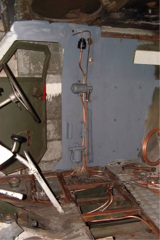 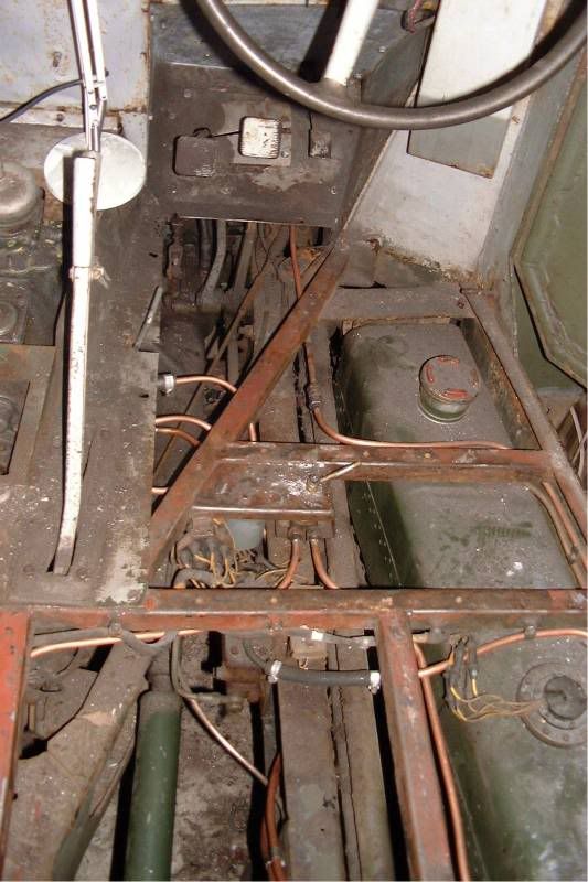
__________________
Clive Elliott GW4MBS (Old) South Wales UK
|
|
#21
10-12-10, 22:11
|
||||
|
||||
|
I have noticed that they do angles, box section and small flat bar etc, which will be useable. However the flat steel sheet would be from a steel merchant I guess, given the sizes required.
You have however been very creative with the microbore copper tubing and compression fittings etc, which did look neat for your fuel lines etc when viewed from underneath FV1609 when I last visited Salisbury. 
__________________
Wayne 1959 Royal Ordnance FV1611A
|
|
#22
11-12-10, 00:41
|
||||
|
||||
|
Quote:
__________________
Wayne 1959 Royal Ordnance FV1611A
|
|
#23
11-12-10, 01:35
|
|||
|
|||
|
I do hope that everyone notices that this will be an RUC pig, not an Army one, as the army ones had side lockers that reached to the front of the rear wheel arches, not just to the top of them. Sorry, not an expert on the FV numbers.
The thread just below on Northern Ireland vehicles provides more detail. Chris
|
|
#24
11-12-10, 17:24
|
|||
|
|||
|
Quote:
__________________
Terry Warner - 74-????? M151A2 - 70-08876 M38A1 - 53-71233 M100CDN trailer Beware! The Green Disease walks among us!
|
|
#25
13-12-10, 01:00
|
||||
|
||||
|
Quote:
I believe that 'Frost Automotive' in the UK do a reasonably priced bench/ vice folder on larger scale than the jaw version posted.
__________________
Wayne 1959 Royal Ordnance FV1611A
|
|
#26
13-12-10, 12:00
|
||||
|
||||
|
I have purchased a duplicate copy of the user handbook for an FV1611A, which I ordered from the Milweb Bookshop.
In the interim of tracking down a genuine UHB it seemed like a good purchase at £14.00 UKP plus postage costs. For those of you who are new PIG owners this may be an option you would consider until that genuine copy becomes available. Sorry about quality of pics / orientation as my 9 month old son was swinging on my arms to grab camera/phone. You will get the gist of it though.
__________________
Wayne 1959 Royal Ordnance FV1611A
|
|
#27
13-12-10, 12:04
|
||||
|
||||
|
Quote:
You are quite right about the lockers. Whilst the shape is different the mechanics of them are similar apart from the RUC/ ARMY/ Development process deviations. I am sure Clive (FV1620) can quote us chapter and verse on the differences and why etc.
__________________
Wayne 1959 Royal Ordnance FV1611A
|
|
#28
13-12-10, 13:18
|
||||
|
||||
|
Quote:
 The wife has asked me what I want for Christmas this year and a pair of 6T (12T pair) HD Ratchet Axle Stands and an Engine Stand are reserved on Santas Sleigh Woop Woop! The wife has asked me what I want for Christmas this year and a pair of 6T (12T pair) HD Ratchet Axle Stands and an Engine Stand are reserved on Santas Sleigh Woop Woop!
__________________
Wayne 1959 Royal Ordnance FV1611A
|
|
#29
14-12-10, 15:38
|
||||
|
||||
|
Yes the side lockers for my RUC Pig are different from the production Pig. But these shorter & less complex lockers are not RUC specific as such.
All of the original 20 FV1609s were like this for Troop Trials in 1956. It was only in 1958 that 10 of these were obtained by the Ministry of Home Affairs for RUC use. All but one of these survived for conversion to hard tops by Belfast Tool & Gauge. The 10 that continued in Army usage were converted to FV1611/12 & uparmoured when the lockers of their various kinds were removed. Most of these ended up as hard targets.
__________________
Clive Elliott GW4MBS (Old) South Wales UK
|
|
#30
14-12-10, 17:56
|
||||
|
||||
|
Quote:
__________________
Wayne 1959 Royal Ordnance FV1611A
|
 |
| Thread Tools | |
| Display Modes | |
|
|


 Linear Mode

