|
|
|
#1
 23-06-13, 11:39
|
||||
|
||||
|
I am getting towards the end of my 221ci Flathead V8 engine rebuild and have a question about HT lead conduits. Could anyone be kind enough to post any images from wartime manuals?
I have a set of British conduits which due to the odd placement of holes I think is for the Lucas Distributor. The ones test fitted in the photo below came from a post 1942 engine with the Crab Distributor as fitted to mine. What I am trying to get to the bottom of is why there are only two holes in the conduit for three plugs (fourth comes out of the end - British conduit has three holes) and what the holes on the inside are for? 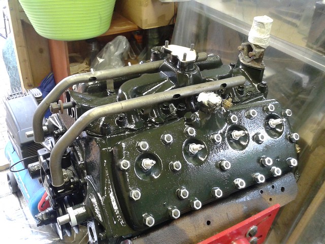 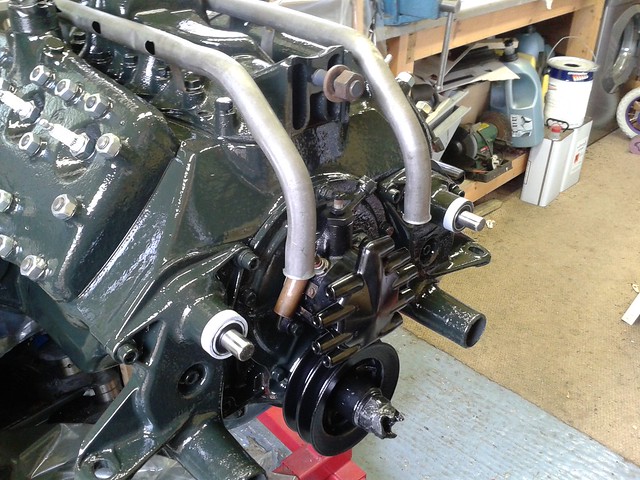 One hole may be for the lead from the coil down to the Distributor.... which brings me on to the location of the coil, I have a special bracket for mounting the bakalite 'Ford' coil above the front of the LH head, whas this ever used in war spec engines? Does anyone have details for the normal layout of the HT system on these 1942-45 USA manufactured engines? I am hoping for parts book images 
__________________
Alastair Lincoln, UK. Under Restoration: 1944 No2 MK2 Loyd Carrier - Tracked Towing 1944 Ford WOT6 Lorry The Loyd on Facebook Last edited by ajmac; 23-06-13 at 11:47. 
|
|
#2
23-06-13, 11:56
|
||||
|
||||
|
Hi,
The conduit with only two holes is for a British engine which has an ignition filter unit bolted to the two cylinder head studs adjacent to where you expect the hole to be, the coil would be along side it. The HT lead for that front cylinder does not appear to come up the tube. cannot post a pic of this at present, but it is Fig 53 in Chilwell manual 63/63 for Universal Carriers. regards, Richard
__________________
Richard 1943 Bedford QLD lorry - 1941 BSA WM20 m/cycle - 1943 Daimler Scout Car Mk2 Member of MVT, IMPS, MVG of NSW, KVE and AMVCS KVE President & KVE News Editor
|
|
#3
23-06-13, 12:26
|
||||
|
||||
|
Quote:
__________________
Richard 1943 Bedford QLD lorry - 1941 BSA WM20 m/cycle - 1943 Daimler Scout Car Mk2 Member of MVT, IMPS, MVG of NSW, KVE and AMVCS KVE President & KVE News Editor
|
|
#5
23-06-13, 14:55
|
||||
|
||||
|
Here are two photos from manuals, the drawing shows the HT leads on a Canadian Mk1, the photo is the British Carrier, with Lucas coil and Ign Filter unit, blocking where the hole in the tube would be and HT lead for No.5 coming straight up from the dizzy.
__________________
Richard 1943 Bedford QLD lorry - 1941 BSA WM20 m/cycle - 1943 Daimler Scout Car Mk2 Member of MVT, IMPS, MVG of NSW, KVE and AMVCS KVE President & KVE News Editor
|
|
#6
23-06-13, 15:47
|
|||
|
|||
|
Alistair, I haven't been through this yet, either. So this is a guess
The British dizzy allows for the leads to cross at the cap. The crab dizzy doesn't, and so leads 3 and 5 must cross over on top of the motor. There are different conduits for the different dizzys, and each has its left and right. So no 5 lead comes from the other side tube (on the inside)etc. See Robert's first picture. I assume you intend to remove your pumps to press the pulleys on?
__________________
Bluebell Carrier Armoured O.P. No1 Mk3 W. T84991 Carrier Bren No2.Mk.I. NewZealand Railways. NZR.6. Dodge WC55. 37mm Gun Motor Carriage M6 Jeep Mb #135668 So many questions.... Last edited by Lynn Eades; 23-06-13 at 15:54.
|
|
#7
23-06-13, 22:12
|
||||
|
||||
|
Thanks to all.
The manual shots with the Crab distributor give all the detail that I require! I never thought to compare the crab distributor HT connections with the firing order. Now I know the RF interference reduction capacitor unit is for the original Ford coil on distributor (divers helmet) arrangement and if I want to fit a UK spec canister coil I need the other radio filter type. Can anyone help me out with that? I do have the Ford coil mount for use with the Bakelite coil as shown the the crab distributor Manual image earlier in this thread. Was this ever used during wartime? Loyd TTs didn't have radios so unless it was a statutory requirement for any kind of tracked carrier perhaps they didn't require HT noise filters.....however the only wartime loyd engine phot that I have does show one fitted on an engine with the coil on distributor setup. Ps. The water pumps are fitted without gaskets just to mask the mating faces during the paint spray. They are already on the bench to have the pulleys pressed on.
__________________
Alastair Lincoln, UK. Under Restoration: 1944 No2 MK2 Loyd Carrier - Tracked Towing 1944 Ford WOT6 Lorry The Loyd on Facebook Last edited by ajmac; 23-06-13 at 23:34.
|
 |
|
|
 Similar Threads
|
||||
| Thread | Thread Starter | Forum | Replies | Last Post |
| Windsor oil system | stephen crowhurst | The Carrier Forum | 4 | 02-04-12 22:57 |
| Exhaust System | gary_bath_jr | The Softskin Forum | 9 | 31-03-12 03:01 |
| P.A. system on arm'd cars? | Dave Block | The Softskin Forum | 5 | 29-01-12 18:18 |
| M38A1 Ignition system question | Casey B | Post-war Military Vehicles | 8 | 25-09-11 05:34 |
| Canadian Suspension system... | Alex Blair (RIP) | The Softskin Forum | 0 | 10-01-05 14:51 |


 Hybrid Mode
