|
|
|
#1
 23-03-16, 01:47
|
|||
|
|||
|
The "Protector, Aerial Base" for Base No.9 was a late addition to prevent the base being destroyed by low branches, etc. A large number of them would have been made up "in theatre" out of materials in hand, so the actual construction could vary considerably.
I think the "BRACKETS AERIAL CLAMPING No.1 T. ZA29558" is for fitting an elevated aerial base to the top of a 'D' rod, since it looks very similar to the "F" rod adapter for the the British 34-ft mast. It's odd in that it has four slotted lugs, which would not appear to match up with the usual aerial bases, and is quite late from its stores code - late 1944-ish. It looks as though it's intended to be rotated onto some studs for clamping, but I don't really see why. It certainly won't fit any of the usual bases, though possibly the No.3/No.16 combination for radio trucks - but the reason for it escapes me at the moment. Chris. 
|
|
#2
23-03-16, 07:49
|
|||
|
|||
|
Hello Chris
The BRACKETS AERIAL CLAMPING No.1 T. ZA29558 is for the top of a vehicle roof, I think??, only reference I've seen for it is in WFTW. Appears to have been used in LCV's and ACV's 4x4 HP RCA/19, one of the aerial connections on the Wireless Sender RCA ET 4332 B includes the following, Connector Single No.46, Insulator W.T. AE Lead-in No.16, Adaptors No.2, 4 or 5, Main Rod Aerials as required. I'm assuming they are referring to 'D' Rods, as the other aerial connection on the RCA set is for a Dipole No.9 which requires something heavier than an 'F' Rod set-up. The above parts are listed in WFTW as being for ACV's & LCV's, also 'D' Rods were originally used for WS 1, 2, 3, 7, 9, and 11; all old school, later the WS22 used 'D' Rods as a 34' antenna/dipole mast set-up for Ground Stations. There is also a reference in the WS53 chapter, picture is poor, ZA number is different ZA.24136 and "it is mounted with 'F' and 'D' Rods to the insulator fitted to the roof'" It also states in WFTW that anything over 18' (6 'D' sections) required stays, 18' is a lot of torque and the Brackets Aerial Clamping would have stabilized the 'D' Rod antenna base/insulator, keeping it from ripping the roof mounting plate out in anything stronger than a light breeze.(Used only when vehicle was stationary) I set up the pieces roughly to give an idea of how they might have worked. The Mounting would have had to be insulated from the vehicle as it is clamped directly to the 'D' Rod. Also the 'F' Rod adaptor would have had to be installed at least one length of rod above the stay plate; as you can not turn the thumb screw on the adaptor when the stay plate is directly under the adaptor. Anyways sort of like this, diameter of bracket is 8 5/16". 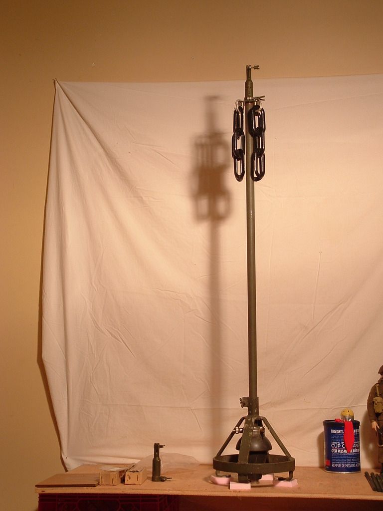 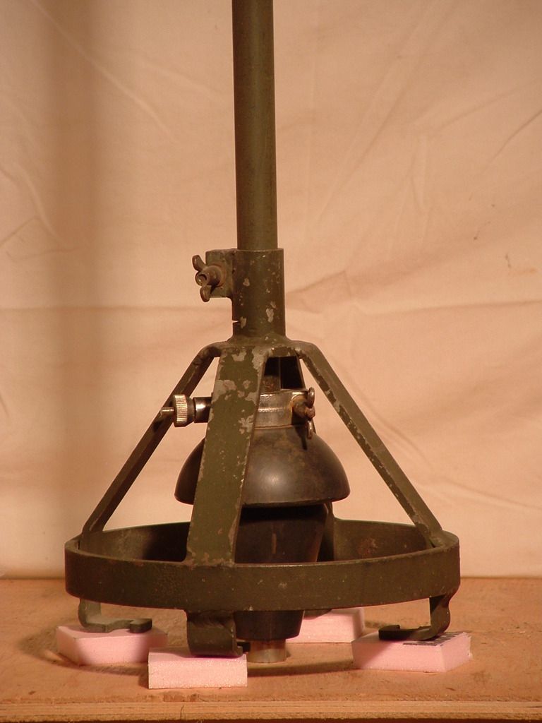 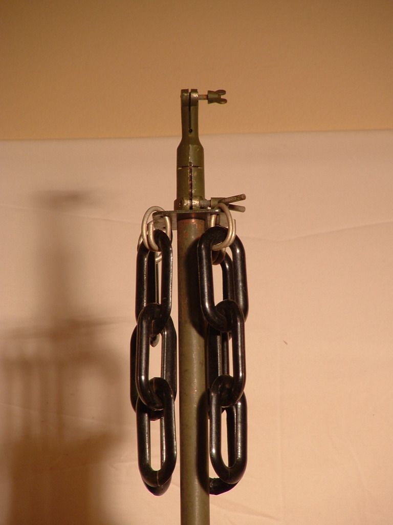 Geoff Last edited by Johnny Canuck; 23-03-16 at 07:55.
|
|
#3
24-03-16, 22:42
|
|||
|
|||
|
Riiiiiiiight.... all becomes clear.
It fits on Aerial Base No.16, which consists of a (modified?) Aerial Base No.3 on top of Insulator W/T "H" (which is a substantial ceramic piece). This was intended for (relatively) high power sets (WS19HP, WS12, WS53, etc) and the Aerial Base No.3 was not up to the job of insulating that much voltage. So: the ceramic (W/T 'H') provides the insulation and feed-through into the vehicle, and the No.3 is bypassed by four braid straps and just acts as a vibration mounting. This is fine for a few 'F' rods, but once you start stacking 'D' rods, the hollow rubber Base No.3 will collapse, so you need that bracket to support the weight of the vertical aerial. Obviously you can't use it on the move, and since it's only supporting the weight of the rods, it doesn't need to be fastened on (certainly not bolted down, anyway). I'm currently cleaning up a Base No.16, and noticed it has four large flat-headed studs on the clamp ring, so that's obviously what the slotted lugs on the bracket mate with. (Drop it on top, rotate into place, feed your first 'D' rod in and tighten the clamps on base and bracket, then add more rods as required. (Or fit the bracket to the assembled vertical before lifting it into position, then slide down, rotate, and clamp in place.)) Once I've got it cleaned up I will see about some photographs of it. Chris. (And that bracket is something else to look for on this side of the pond.) 
|
|
#4
28-03-16, 01:14
|
|||
|
|||
|
Aha! I seem to have two variants of Aerial Lead-in No.16, plus the mounting hardware for both types.
The first type is for "15cwt 4 wheeled Wireless Truck Mk.III" and fits on a bracket over the cab. Feed is via a "blackout box" on the end wall and an "Insulator W/T lead in No.12" (two glass dome insulators in a square panel). The four braid straps that bypass the rubber insulator on Base No.3 are fitted to the top clamping ring. See WftW Vol.2 Page WS19-74 which is for a (British) WS19HP install. The second type is for "House Type Body" wireless trucks (15 cwt Mk.II), LCV and ACVs, and the post-WW2 Austin K9. This fits to a paxolin plate in the centre of the roof and is fed directly through the base. (It allows the safe use of rather higher powered transmitters like the WS53 and RCA 4332 and BC-610, where the feeder can go straight up from the set to the base and be protected by an earthed metal guard.) For this version, the braid straps are fitted to the plate that the Base No.3 is clamped to, and the clamping ring has gained the studs that the "Bracket, Aerial Clamping" fits onto. (It has to rotate anticlockwise (viewed from above) because the studs for the (now unused) braid connections are next to the new ones for the aerial bracket.) Photographs of all this stuff once I get the camera sorted out and the "first type" of base unearthed and cleaned up! Chris.
|
|
#5
28-03-16, 21:37
|
|||
|
|||
|
Quote:
Chris.
|
|
#6
12-12-17, 05:38
|
||||
|
||||
|
Just had these arrive in the mail.
The left one I've seen before but the right one I've never seen. It looks to be a manufacturers instruction booklet. Comparing the two there are a number of different diagrams for setting of the antenna.
__________________
Jordan Baker RHLI Museum, Otter LRC C15A-Wire3, 1944 Willys MB, 1942 10cwt Canadian trailer
|
|
#7
12-12-17, 20:33
|
|||
|
|||
|
Quote:
I think it refers to an earlier version of the mast, since although they are both described as P.C. 84295C they have a different -nnn suffix. I'd be interested in a scan of the component list because I have a cast alloy/ceramic insulator with that PC number on it that is neither the ebonite base insulator nor the ceramic type that replaced the ebonite one for use with the WS52 - I suspect it was the original insulator and turned out to be insufficiently soldier-resistant. (The later Mast, Telescopic, 27-ft for the Larkspur range has a very similar design but a more substantial ceramic insulator in the middle. Chris.
|
|
#8
23-12-19, 11:31
|
|||
|
|||
|
In August I purchased a Lynx I MkIII*. This came complete with a 19 set. I have now got the vehicle in a state ready for the road and am looking at the ancillary equipment.
The vehicle has one section of an antenna fitted to the base on the near (left hand) side. With the vehicle came two more sections of an antenna. I have two questions. Is the complete antenna composed of 3 sections? How do I separate these two sections? I have attached a picture of the join. There seems to be a rolled thread just below the join. Does the solid top section just unscrew or should it telescope inside the lower section? Thank you Alastair F60S LynxI MkIII*
|
|
#9
23-12-19, 13:21
|
|||
|
|||
|
Quote:
It should just pull out, but if it's rusted in place you may have difficulty extracting it without soaking it in oil and possibly applying heat. The to section can be clamped in a vice, but you can't do much about the lower section as it's thin wall steel tube and quite fragile. (The rolled-in thread was a WW2 Canadian improvement to the British aerial rods which were just a push fit and tended work loose and fall out when bounced around.) The first (bottom) rod has a solid butt end and no threaded portion because it clamps into the aerial base (or adapter) and needs to be un-crushable, the other rods have a threaded portion at the butt end and a rolled-in thread (for retention on the move) at the top. The threaded ones are 49.5 inches long rather than the original 48-inch specification. Chris.
|
|
#10
23-12-19, 13:28
|
|||
|
|||
|
Quote:
 The usual mobile aerial was 2 sections (less danger of being damaged by low branches), but 3 could be used if extra range was required. Maximum (sensible) length is 4 sections (base, two middles and a top), but that is strictly for stationary use - it's too fragile for driving around with and might damage the aerial base with the extra leverage applied. Chris.
|
|
#11
23-12-19, 13:53
|
|||
|
|||
|
Quote:
1) soak the joint with penetrating oil for a while. 2) remove the bottom aerial section from the aerial base on your vehicle. 3) fit that to the other two sections (assuming it's the type with the rolled-in thread and a solid butt), and screw it together (hand tight only). 4) clamp the top (stiff wire part) in a vice. 5) If you have an old aerial base or one of the adapters, clamp the bottom section in that (or use a clamp and wooden blocks), then pull on the bottom section and tap the clamp (or whatever) gently with a hammer towards the bottom of the aerial. (What you really need is a slide-hammer with a collet that will take the aerial, but no such animal exists.) With luck it will separate the push-fitted top section. Best regards, Chris.
|
 |
| Thread Tools | |
| Display Modes | |
|
|
 Similar Threads
|
||||
| Thread | Thread Starter | Forum | Replies | Last Post |
| Wireless of the Week - week 1 | Bruce Parker (RIP) | The Wireless Forum | 4 | 17-07-16 00:45 |
| Wireless of theWeek - week 4 | Bruce Parker (RIP) | The Wireless Forum | 5 | 12-03-16 15:45 |
| Wireless of the Week - week 3 | Bruce Parker (RIP) | The Wireless Forum | 11 | 07-03-16 02:16 |
| Wireless of the Week - week 2 | Bruce Parker (RIP) | The Wireless Forum | 5 | 28-02-16 16:54 |
| How Far Did You Drive Your CMP This Week | Phil Waterman | The Restoration Forum | 6 | 23-05-07 03:37 |


 Hybrid Mode
